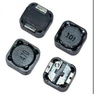
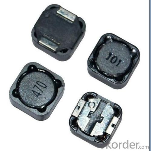
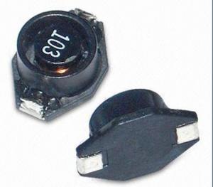
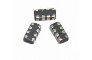
PBH Series SMD Power Inductor
- Ref Price:
-

- Loading Port:
- China Main Port
- Payment Terms:
- TT or LC
- Min Order Qty:
- 1000 Pieces pc
- Supply Capability:
- 20,000 Pieces per Day pc/month
OKorder Service Pledge
OKorder Financial Service
You Might Also Like
1. pbh series smd power inductor
2. Rated current: 1-10A
3. Inductance0.5~6000uH
4. ROHS
5. competitive price
Features:
1.SMD Power Inductor
2.Magnetic shieled surface mount inductor with high current rabing low D.C resistance
3.Excellent terminal strength
4.Packed in embossed carrier tape and can beused by automatic mounting machine.
5.Various hogh power inductors are superior to be high saturation for suiface mounting.
Applications:
Power supplu for VTR,OA equipment Digital camera, LCD television set notebook PC,
portable communication equip,ents, DC/DC converters, etc.
- Q:An inductor that has an inductance of 24 H and a resistance of 41 ? is connected across a 120 V battery. What is the rate of increase of the current at 0 s. Answer in units of A/s.What is the rate of increase of the current at 0.7 s.Answer in units of A/s.
- Back emf,e L.di/dt where L inductor, di/dt is the rate of change of current. And Z^2 R^2 + XL^2 where Z is impedance, R is the resistance and XL is the inductive reactance. Z^2 41^2 + (2pi*60*24)^2 [Assuming line frequency, f 60 Hz) Z^2 1681 + 8985.6 10666.5 Z 103.27 ohms. Now the total current ,I 120/ Z 120/ 103.27 1.162 amps. Again, T L/R where T Time constant 24/41 .58 sec which is one time constant' In this period, the current flows 63% of the full current 1.162 amp .73 amps. For full current of 1.62 to flow is the time, 5T .58*52.9 sec.And discharge current is 37% 1.162*.37 .59 amps, During this period, back emf occurs Hence the back emf,e .59*sqrt8985.6 or,e .59*94.7 55.8 volts at this voltage, then at .7 sec, di/dt .59/.7 .84 amp/sec at 0 sec, di/dt .84/0 infinity that is like a short circuit current. I think this is the answer. Thank you.
- Q:I am wanting to build an inductor to certain specs.The inductor will operate in the audo frequencies of about 5-20kHz and be wound on an iron core. I need an inductance of about 150mH.How do I determine what type of core I need, what wire size, and the number or turns of wire will be required to make the inductor?Any help or references will be appreciated!
- L u0 ur N^2 A/length Where L is the Inductance and u0 4pi x 10^-7 and ur is the relative permeability of the core material (which should stay constant with current fluctuations) and N is the number of turns and A is the cross sectional area of the core and l is the magnetic path length. . all in SI units. The wire size will depend of how much current the winding has to tolerate without getting too warm. DON'T DO IT! There are so many factors that you'll wish you had never tried. Buy the inductor you need from an electronics shop and make sure its power rating can cope. Don't use an iron core - it will not be able to cope with the higher audio frequencies. A powdered-iron toroid might be best
- Q:and whyalso does that work when you open circiut a capacitor.
- Remember that when a component is shorted, the situation is effectively the same thing as taking a wire from one terminal of the component to the other. That is, it's like having a wire in parallel with the component itself. Current flows through the short (or wire) instead of through the component. This is as true in AC circuits as it is in DC circuits. So if an inductor (or any other component) is shorted, then any component in parallel with it will also be shorted because it will also not have any current flowing through it. Components in series will not be shorted provided the short starts at one of the inductor's terminals and ends the other.
- Q:A constant voltage of 4.00 V has been observed over a certain time interval across a 2.20 H inductor. The current through the inductor, measured as 1.00 A at the beginning of the time interval, was observed to increase at a constant rate to a value of 6.00 A at the end of the time interval. How long was this time interval?
- e? Ldi/dt 4 2.20. 1/dt or, dt 2.20/4 .55 s Considering ,e?, L, the same . Or, 4 2.20. 6/dt1 or, dt1 13.2/43.3 s The time interval between 3.3 s .55 s 2.75. And the total time interval 3.3 + .55 3.85 s
- Q:I have a few handfuls of scavenged inductors that I really want to know the inductance of. Some of the air-core inductors I've been able to somewhat successfully (worked in filters I made with them and etc) ballpark the value using formulas and programs from electronics sites. However, that really only works with the ones I am able to figure out the wire gauge and from there the number of layers, and the inner/outer circumference of the core. Also, I have a fair number of ferrous-core inductors that I can't measure either. I don't have the money or resources currently for an oscilloscope or signal generator, although I suppose I could just put together a quick oscillator for a signal to useanyway, isn't it possible to just measure the current through the inductor (or maybe with a known value capacitor too) with 60-hertz line frequency with a known (obviously lower than line) voltage? Then calculate the combined reactance/impedance etc?
- The resistor is used to sense the current.
- Q:A 12.6 V battery is in series with a 30.0 mH inductor and 0.150 ohm resistor connected through a switch. When the switch is closed at t o, find time constant of the circuit( ans: 0.2 s) Find the current after 1 time constant has elapsed ( ans: 53.1 A) Find the voltage drop across R after t0 and after one time constant ( ans: 0 volts and 7.97 V ) find rate of change of current after one time constant( ans: 150 A/s)I have the answers, but I need a step by step? I'd appreciate any help.
- Let V_s the voltage of the battery 12.6 V Let i the current through the series circuit Let R the resistance of the resistor 0.150 Ω Let L the inductance of the inductor 0.03 H Let V_r the voltage across the resistor (i)R Let V_l the voltage across the inductor L(di/dt) The source voltage must equal the sum of the voltages across the components: V_s V_r + V_l 12.6 V (i)R + L(di/dt) di/dt + (i)(R/L) (12.6 V)/L The integrating factor for this is e^{∫ (R/L)dt} e^{(R/L)t} e^{(R/L)t}di/dt + e^{(R/L)t}(i)(R/L) e^{(R/L)t}(12.6 V)/L The left side integrates as the reverse of the product rule and the right side integrates with the reciprocal of the coefficient with a constant, C: e^{(R/L)t}(i) e^{(R/L)t}(12.6 V)/R + C Multiply both sides by e^{-(R/L)t}: (i) (12.6 V)/R + Ce^{-(R/L)t} i (12.6 V)/0.150 Ω + Ce^{-(R/L)t} i 84 A + Ce^{-(R/L)t} We find the value of C by knowing that i 0 at t 0 0 84 A + Ce^0 C - 84 A i (84 A)(1 - e^{-(R/L)t}) To find the time constant set (R/L)t 1: t L/R 0.03/0.150 0.2 s One time constant means that -(R/L)t -1 i (84 A)(1 - e^-1) ≈ 53.1 A The current is 0 at t 0 so V_r R(0) 0 The current is 53.1 A at t 0.2 s so V_r (0.150 Ω)(53.1 A) ≈ 7.97 V The charge rate is di/dt and we have an equation involving that: di/dt + (i)(R/L) (12.6 V)/L Solve for di/dt: di/dt (12.6 V)/L - (i)(R/L) di/dt 12.6 V/0.03 H - (53.1 A)(0.150 Ω/0.03 H) di/dt 154.5 A/s
- Q:An RLC circuit with a capacitance of 0.010 uF is found to resonant with a frequency of 1.30×10⁴ Hz. What is the value of the inductor? Also what are the units of the inductor. Thanks
- X ind2TTfL , X cap1/(2TTfC), at resonance,X ind Xcap,2TTfL1/(2TTfC), 4TT^2f^2LC1, L1/(4TT^2 f^2 C)1/[4TT^2 (13000)^2 (0.01 x 10^-6)] L0.014988 henry14.98 mili-henry God bless you.
- Q:i wanna build a 50 uH inductor for 220 volt and 1 A. which core would be good for this purpose? I will really appreciate your help.
- 1 amp and you need at least #20 wire. Inductance of a solenoid, air L ??N?A/Ln Ln is length in meters A is cross-sectional area in meters? N is number of turns ?? is the magnetic constant 1.2566×10?6 H/m (or T·m/A) assuming a coil 1 cm in diameter and 2 cm long A 0.0000785 m? L 0.02 m 50? (1.26e-6)(0.0000785)N? / (.02) N 100 turns a bit large for practicality. But if you extend the length to 5 cm, that brings the number of turns to 40, that can be done.
- Q:a)A capacitor offers infinite resistance to AC and Inductor to DC b)A capacitor offers infinite resistance to DC and Inductor to ACc)A capacitor offers no resistance to DC and Inductor to DCd) A capacitor offers infinite resistance to DC and Inductor offers no resistance to ACpls send me the correct answer and the reason for the answer ?
- Answer b) is true. Intuitively: Capacitors store potential energy. At DC a finite voltage may apply but no current can flow through the disconnected plates. By Ohm law definition, that is an infinite resistance at DC. Inductors store kinetic energy which prevents the current from changing. At high frequencies the voltage may change “freely” while the current does not change much. By definition, that is (a large voltage change divided by a zero current change) an infinite resistance at AC.
- Q:Hi, can somebody please help me with this inductor problem? I'm stuck on it and need some help i think that I have the general idea, but need some guidance.
- This is a step-value function and will need to be solved piece-wise. For t 0 to 5us: Since I (1/L) Vdt therefore:: I (1 / 2E-3) * 10V * 5us 500 * 10V * 5us 25mA For t 5us to 15us I (1 / 2E-3) * -10V * 10us 500 * -10V * 10us -50mA For t 15us to 20us I (1 / 2E-3) * 10V * 5us 500 * -10V * 5us 25mA The total current from t 0 thru t 20us 25mA -50mA +25mA 0 mA
1. Manufacturer Overview |
|
|---|---|
| Location | Guangdong,China (Mainland) |
| Year Established | 2010 |
| Annual Output Value | US$10 Million - US$50 Million |
| Main Markets | North America; South America; Eastern Europe; Southeast Asia; Africa; Oceania; Mid East; Eastern Asia; Western Europe |
| Company Certifications | ISO 9001:2000 |
2. Manufacturer Certificates |
|
|---|---|
| a) Certification Name | |
| Range | |
| Reference | |
| Validity Period | |
3. Manufacturer Capability |
|
|---|---|
| a)Trade Capacity | |
| Nearest Port | |
| Export Percentage | 41% - 50% |
| No.of Employees in Trade Department | |
| Language Spoken: | |
| b)Factory Information | |
| Factory Size: | |
| No. of Production Lines | |
| Contract Manufacturing | OEM Service Offered Design Service Offered Buyer Label Offered |
| Product Price Range | |
Send your message to us
PBH Series SMD Power Inductor
- Ref Price:
-
- Loading Port:
- China Main Port
- Payment Terms:
- TT or LC
- Min Order Qty:
- 1000 Pieces pc
- Supply Capability:
- 20,000 Pieces per Day pc/month
OKorder Service Pledge
OKorder Financial Service
Similar products


New products
Hot products

Hot Searches

