

Steel I Beam Bar IPE for Structure Construction Normal Sizes
- Ref Price:
-

- Loading Port:
- Tianjin
- Payment Terms:
- TT OR LC
- Min Order Qty:
- 25 m.t.
- Supply Capability:
- 10000 m.t./month
OKorder Service Pledge
OKorder Financial Service
You Might Also Like
1. Structure of Steel I Beam Bar IPE Description:
Steel I beam bar IPE is a beam with an I-shaped cross-section. The horizontal elements of the "I" are known as flanges, while the vertical element is termed the "web". Steel I beam IPE is usually made of structural steel and is used in construction and civil engineering. The web for Steel I beam IPE resists shear forces, while the flanges resist most of the bending moment experienced by the beam. Steel I Beam IPE theory shows that the I-shaped section is a very efficient form for carrying both bending and shears loads in the plane of the web.
2. Main Features of Steel I Beam Bar IPE Form:
• Grade: Q235
• Type: Mild carbon steel
• Deflection: The stiffness of the I-beam will be chosen to minimize deformation
• Vibration: The stiffness and mass are chosen to prevent unacceptable vibrations, particularly in settings sensitive to vibrations, such as offices and libraries.
• Local yield: Caused by concentrated loads, such as at the beam's point of support.
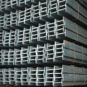
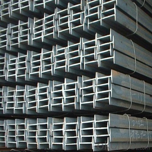
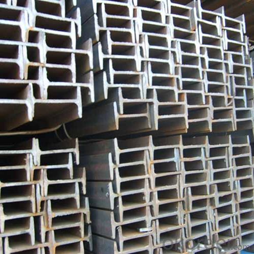
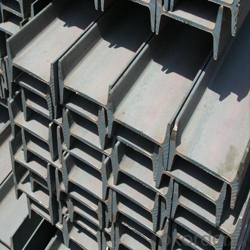
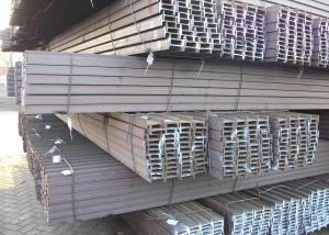
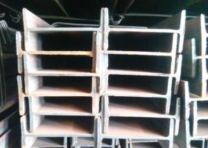
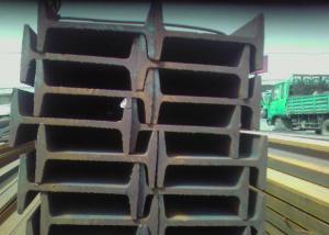
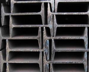
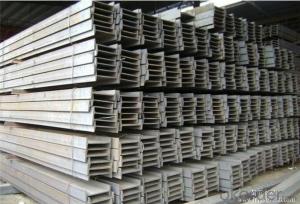
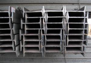
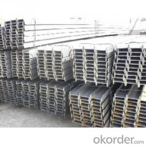
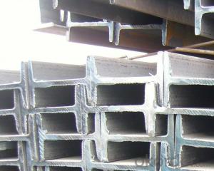
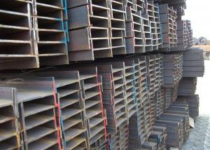
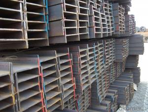
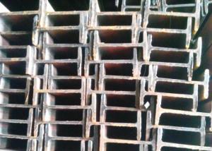
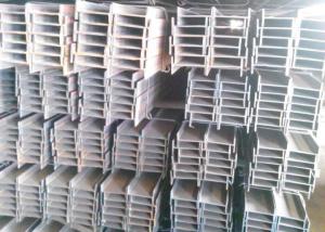
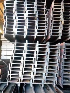
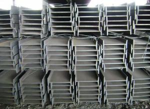
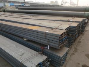
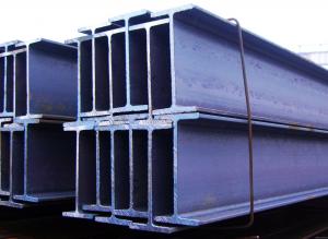
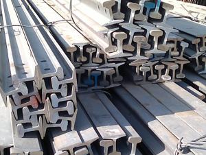
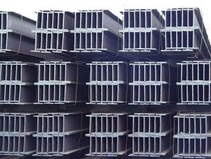
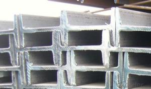
3. Steel I Beam Bar IPE Images:


4. Steel I Beam Bar IPE Specification:

5. FAQ
We have organized several common questions for our clients,may help you sincerely:
①Is this product same as W beam?
In the United States, the most commonly mentioned I-beam is the wide-flange (W) shape. These beams have flanges in which the planes are nearly parallel. Other I-beams include American Standard (designated S) shapes, in which flange surfaces are not parallel, and H-piles (designated HP), which are typically used as pile foundations. Wide-flange shapes are available in grade ASTM A992,[4] which has generally replaced the older ASTM grades A572 and A36.
②How to inspect the quality?
We have a professional inspection group which belongs to our company. We resolutely put an end to unqualified products flowing into the market. At the same time, we will provide necessary follow-up service assurance.
③Is there any advantage about this kind of product?
Steel I beam bar IPE has a reduced capacity in the transverse direction, and is also inefficient in carrying torsion, for which hollow structural sections are often preferred.
- Q: How do steel I-beams perform in terms of vibration insulation?
- Despite their excellent structural strength and load-bearing capacity, steel I-beams may not be the most effective choice when it comes to vibration insulation. Their rigid and inflexible nature tends to transmit vibrations rather than absorb or dampen them. Consequently, when exposed to vibrations caused by heavy machinery, earthquakes, or nearby traffic, steel I-beams can propagate these vibrations throughout the structure, potentially causing discomfort, noise, and even structural damage. To enhance the vibration insulation capabilities of steel I-beams, various measures can be taken. One commonly used approach is the incorporation of vibration isolation materials or techniques. These can involve the utilization of specialized rubber pads, foam inserts, or flexible connectors positioned between the steel beams and the surrounding structure. These materials and techniques are specifically designed to absorb and dampen vibrations, thereby reducing their transmission through the building. Another option involves implementing structural modifications that enhance the vibration insulation properties of steel I-beams. For instance, adding additional mass to the beams, such as by attaching concrete or other heavy materials, can help mitigate the transmission of vibrations. Additionally, introducing damping elements like tuned mass dampers or viscoelastic materials can effectively dissipate and attenuate vibrations, ultimately improving the overall vibration insulation performance. It is important to recognize that although steel I-beams may not possess inherent vibration insulation capabilities, they are often preferred for their strength, durability, and cost-effectiveness in structural applications. Therefore, a combination of appropriate design, engineering, and additional measures can be employed to minimize the adverse effects of vibrations and optimize the vibration insulation performance of steel I-beams.
- Q: What is the typical lifespan of steel I-beams?
- The typical lifespan of steel I-beams can vary depending on several factors such as the quality of the steel used, the environment in which they are installed, and the level of maintenance provided. However, under normal conditions, steel I-beams are designed to have a very long lifespan. In general, they can last for several decades, if not longer, without any significant deterioration or structural issues. With proper care and maintenance, including regular inspections and necessary repairs, steel I-beams can remain structurally sound and functional for a very long time. It is important to note that factors such as exposure to corrosive environments or excessive loads can potentially shorten the lifespan of steel I-beams, so it is crucial to consider these factors when assessing their longevity. Additionally, advancements in steel manufacturing and coating technologies have further improved the durability and longevity of steel I-beams, making them even more reliable and long-lasting.
- Q: Do steel I-beams require any special maintenance?
- Yes, steel I-beams do require regular maintenance to ensure their structural integrity and longevity. This includes inspecting for signs of corrosion, checking for any cracks or damage, and applying protective coatings or treatments to prevent rust. Additionally, proper cleaning and lubrication of any moving parts or connections is necessary. Regular maintenance ensures the optimal performance and safety of steel I-beams.
- Q: How do you calculate the cost of steel I-beams?
- To calculate the cost of steel I-beams, several factors need to be considered. Firstly, the weight of the beam is a crucial element. The weight of an I-beam is determined by its dimensions, including the height, width, and thickness of the flanges and webs. This information can be obtained from a steel manufacturer or supplier. Next, the price per pound or per kilogram of steel needs to be determined. Steel prices can vary depending on factors such as market demand, availability, and location. It is advisable to contact multiple suppliers or check online platforms to get the most accurate and competitive prices. Once the weight of the I-beam and the cost per unit weight are known, the total cost of the steel I-beam can be calculated by multiplying the weight by the cost per unit weight. For example, if the weight of the I-beam is 500 pounds and the cost per pound of steel is $1.50, the total cost would be 500 pounds x $1.50/pound = $750. It's important to note that additional costs such as transportation, taxes, and any specialized cutting or fabrication services should also be considered when calculating the overall cost of steel I-beams. Therefore, it is recommended to consult with suppliers or professionals to get a comprehensive estimate on the total cost of steel I-beams.
- Q: What are the different types of connections for steel I-beams?
- There are several different types of connections for steel I-beams, including welded connections, bolted connections, and moment connections. Welded connections involve fusing the I-beam to other structural elements using heat and welding techniques. Bolted connections involve using bolts and nuts to secure the I-beam to other components. Moment connections are specialized connections that allow the I-beam to resist bending moments and transfer loads effectively.
- Q: Can steel I-beams be used to create open floor plans in buildings?
- Yes, steel I-beams can be used to create open floor plans in buildings. Steel I-beams are known for their strength and versatility, allowing for the construction of large, open spaces without the need for numerous supporting columns or walls. Their ability to span long distances and support heavy loads makes them an ideal choice for creating open floor plans in buildings.
- Q: Can steel I-beams be used in architectural designs?
- Yes, steel I-beams can be used in architectural designs. Steel I-beams are commonly used in construction and are known for their strength and load-bearing capacity. They are often used in the construction of bridges, high-rise buildings, and other large structures. The use of steel I-beams allows architects and engineers to create designs with open and spacious floor plans, as they can support heavy loads and span long distances without the need for additional support columns or walls. Additionally, steel I-beams are durable and resistant to fire, making them suitable for various architectural applications.
- Q: What are the different types of steel I-beams?
- There exists a variety of steel I-beams, each designed to fulfill specific structural needs and requirements. Some of the most prevalent types include: 1. W-Beam: The most commonly utilized I-beam, it features a wide flange section resembling the letter "W". It offers exceptional support and load-bearing capabilities, allowing for a wide range of applications. 2. S-Beam: Also known as American Standard Beams, S-beams possess a narrower flange section resembling the letter "S". They find common usage in residential construction and light to medium-duty applications. 3. HP-Beam: HP-beams, or H-piles, showcase a wider flange section and are predominantly employed in deep foundation applications, such as supporting large structures or bridges. They exhibit excellent load-bearing capacity and resistance to lateral forces. 4. M-Beam: M-beams, or miscellaneous beams, typically cater to smaller-scale applications or situations necessitating specific load requirements. They come in various sizes and are frequently employed in the construction industry for framing, support structures, and similar applications. 5. L-Beam: L-beams, also known as angle beams, consist of two legs forming an L-shape. Primarily used for structural purposes, they provide support for columns, beams, or act as braces in construction projects. 6. C-Beam: C-beams, or channel beams, feature a C-shaped cross-section and are commonly utilized for structural purposes, such as framing, support, or as tracks for sliding doors or windows. These examples represent only a fraction of the diverse steel I-beams available. It is crucial to select the appropriate type based on project-specific requirements, including load-bearing capacity, span, and structural needs. Consulting with a structural engineer or steel supplier can aid in determining the most suitable I-beam type for a particular application.
- Q: Can Steel I-Beams be used for elevator shafts?
- Indeed, elevator shafts can indeed utilize Steel I-Beams. In construction, Steel I-Beams are frequently employed due to their robustness and ability to bear heavy loads. The weight of an elevator car, counterweights, and passengers necessitates the use of sturdy and resilient materials in elevator shafts. Steel I-Beams furnish the essential structural integrity and support needed for elevator shafts, guaranteeing the safety and stability of the entire elevator system. Furthermore, steel proves to be a long-lasting material capable of enduring the continuous movement and vibrations associated with elevator operation. Consequently, Steel I-Beams present a suitable option for the construction of elevator shafts.
- Q: What is the maximum span length for a steel I-beam?
- The maximum span length for a steel I-beam depends on various factors such as the size and type of the I-beam, the load it needs to support, and the desired deflection criteria. Generally, steel I-beams can span up to 60 feet or more, but it is recommended to consult structural engineers or reference design tables to determine the specific maximum span length for a particular I-beam.
Send your message to us
Steel I Beam Bar IPE for Structure Construction Normal Sizes
- Ref Price:
-
- Loading Port:
- Tianjin
- Payment Terms:
- TT OR LC
- Min Order Qty:
- 25 m.t.
- Supply Capability:
- 10000 m.t./month
OKorder Service Pledge
OKorder Financial Service
Similar products
Hot products
Hot Searches
Related keywords

