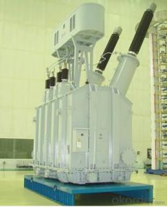

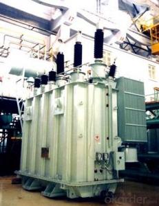
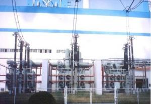
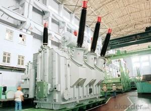
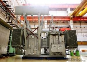
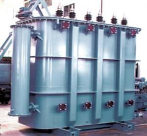
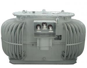
31.5MVA/220kV single phase traction transformer
- Ref Price:
-

- Loading Port:
- Tianjin
- Payment Terms:
- TT OR LC
- Min Order Qty:
- 1 pc
- Supply Capability:
- 1 pc/month
OKorder Service Pledge
OKorder Financial Service
You Might Also Like


Quick Details
| Place of Origin: | HeBei | Brand Name: | CNBM | Model Number: |
|
| Usage: | Power | Phase: | Three | Coil Structure: | Toroidal |
| Coil Number: | 3 Winding | Capacity: | Rated Voltage: | 31.5MVA/220kV | |
| Connection Symbol: | YNd11 Dyn11 YNyn0d11 | Tank: | Cover type or Bell type | OLTC: | MR or ABB or SMS |
Packaging & Delivery
| Packaging Detail: | Mainbody --naked Disassembled parts -- crate |
| Delivery Detail: | 3 months |
Specifications
1. CESI certificate
2. High short-circuit withstand
3. Low loss, PD and noise
4. CTQC certificate
5. No leakage
Description
The application of the 31.5MVA/220kV single phase traction transformer, and matches well with the transmission capacity of UHV lines, which has wide prospect of application. Because of its large capacity and large volume, the whole transportation weight with nitrogen is about 470-490 tons, and due to the restricted transport conditions, the transportation becomes the critical issue for application of the 31.5MVA/220kV single phase traction transformer. In order to make the products applicable to any UHV substation in our country, the state grid of corporation of China set the "A study of easy-transport large capacity UHV Transformer” as a key scientific research projects, and entrusted BTW to carry out the research.
During the process of research and development, BTW adopted the advanced design technology and modular design, the transformer can be transported disassembly and with advantages of compact core and winding body, less transportation weight and low transportation cost, effectively solves the need of UHV construction in the transportation restricted areas. By using the most advanced 3D magnetic field calculation software, BTW performed detailed analysis and calculation for the magnetic flux leakage and eddy current loss of the transformer coil, iron core and oil tank steel structures. Besides, by using of the advanced electric field calculation software, BTW performed detailed analysis and calculation of main longitudinal insulation, and mastered the arrangement of the main longitudinal insulation of large capacity UHV transformer and the control of distribution of winding magnetic flux leakage. All of which make the products with low loss, low noise, small volume, strong anti short circuit ability, no local overheating and other significant advantages, and guarantee the long-term safe and stable operation.
The world's first on-site assembled large capacity UHV Transformer’s right at the first time once again filled the gap in the field of UHV transformer research after Chinese transformer industry overcame the difficulty of integral transport of the 31.5MVA/220kV single phase traction transformer, which marks BTW has fully occupied the world transformer industry technical peak. The successful development of the product filled the gaps in the domestic technology and met the urgent need of UHV construction application in our country, greatly improved the technical level and manufacturing ability of BTW in terms of UHV Transformer products.
- Q: I have a packaged heat pump w/ Emergency Heat that is not working and does not come on at all. No lights or anything even when I switch it to emergency heat. Someone said that it could be my low voltage transformer. What is that and how do I check it?
- A low voltage transformer on an a/c and heat system is a device that lowers the line voltage down to a safe 24 volts to run in control wiring to your thermostat to control your system. If your thermostat has a removable cover where you can see the wires underneath it is easy to see if you have no low voltage as long as you have a volt meter that can measure 24 volts ac. Make sure the thermostat is off and measure the voltage from R to any other terminal and you should read 24 volts nominal (more likely somewhere around 27) If you don't read 24 volts minimum you have a problem in the low voltage circuit. Most heat pumps will have some kind of low voltage protection such as a fuse or small circuit breaker in the unit so it doesn't necessarily mean the transformer is blown. The more important thing is to find the reason that caused it and that requires thorough understanding of the system. It's really best to have a technician diagnose this kind of problem.
- Q: If the primary circuit of a transformer is connected to a power source and the secondary circuit has a light bulb, will the light bulb turn on and stay on when the power source is turned on? Or will it turn on for a few seconds and then turn off?This question's been bugging me because I think because transformers are usually wired through AC that the bulb would only turn on for a few seconds and then turn off, but then shouldn't current be constantly flowing so it would stay on?Thanks for and clarifications.
- Umm, is the power source AC or DC? You are right, transformers usually use AC. Is it not using AC in this example? You didn't say. If it's using AC, the light bulb will stay on. The current actually switches on and off, but so fast you don't see it. Well, normally, for household 60Hz AC power. But who knows with this mystery power source. It could be 1Hz AC. If it's using DC, then it will come on for a short time (a few seconds? I don't know). Yes, current is continually flowing through the primary circuit, but after a while no current will be flowing through the secondary circuit where the light bulb is connected. It takes change in current in the primary circuit to induce a current in the secondary circuit.
- Q: What is the meaning of the high voltage side and the low side of the transformer?
- Under normal circumstances the role of the transformer is to high-voltage transmission (saving material to reduce the loss) over the power to reduce the voltage (there are boost in the power plant substation) to meet the conventional use of electrical equipment standards. Therefore, in the conventional step-down transformer input (also called once) is the high-pressure side, the output (also called the second) is the low side.
- Q: I'm building a ark welder and i know they get very hot, iv seen some people in ''the internet'' submerging their transformers in transmission fluid to keep em cool under excessively heavy work loads.My question is what effects does oil have on wire insulation?And what about the transformer varnish and core insulation wads and paper?
- Your right to be cautious. There could be water, metal, plastics in transmission fluid. Used or new. It is designed to help cool a transmission among other tasks. They use oils and other things in power transformers up on power poles. I know cause one near me leaked. A junk yard might sell you that fluid. A letter to the varnish and paper maker might give you a clue.
- Q: I have an old xray machine with a large step down transformer.Its not shorted but the paper insulation looks to dry. Is there a special oil for this? Thanks.
- there is no oil for transformers. they are kept dry by all the heat they generate. it cooks the moisture out. if there is a specific reason you are worried, please do tell. is it going to be stored or go unused for a while? is there a lot of moisture in the area of operation? if not, i would not worry about it. it sounds as if it might be near the end of its life cycle as is. on the bright side transformers dont just burn out. there must be a reason for the failure. moisture is not too bad, but water is.
- Q: A stepdown transformer is used for recharging the batteries of portable devices such as tape players. the turns ratio inside the transformer is 13:1 and it is used with 120 V rms household service. if a particular ideal transformer draws 0.350 A from the house outlet, what are the voltage and the current supplied to a tape player from the transformer. How much power is delivered?
- Tape Player Transformer
- Q: Find full load current of transformer. What do it mean by full load current? 100% efficiency, or maximum load in secondary winding?Let R1 32ohm, R20.05ohm, X1 45ohm, X2 0.06ohm.1 is in primary and 2 in secondary winding.R0250kohm, Xm 30kohm(R0 and Xm are the values refered to primary)How to calculate the full load current?
- there are many criterion it is application dependant or power it is the load that causes a temperature rise that if loaded beyond it will cause failure of course it depends on the insulation material so a smaller transformer could have a much higher rating because it can stand more heat small electronic stuff will generally be when the transformer can no longer sustain the output voltage Anita
- Q: i m studying about the non linearity in systems and transformer is non linear in nature
- drop the voltage to the rated value otherwise it will be burnt.
- Q: How does a step down transformer decrease the output voltage but increases the output current? And how does the step up transformer does the opposite thing?
- Transformers function as electrical gearboxes to give an analogy. The product of current through the winding and voltage across the winding is the same for both the input winding and the output winding, due to conservation of energy. Transformers trade voltage for current, while, if ideal, preserving transferred power. The way a transformer works, is that when there is a changing magnetic field produced by the input winding (due to a derivative of current through this winding) induces a voltage across the output winding, as per Faraday's law of induction. Because of the self-inductance of the input winding, since it is after all an inductor, the voltages across both windings are both in phase. The higher the frequency used, the better and more efficient the transformer works. To make them work at lower frequencies, it is necessary to make bigger overall windings with larger inductance values. The stepping ratio is set by the number of coils of wire in both windings. The number of coils on the output winding divided by the number of coils on the input winding gives the stepping ratio. Should the stepping ratio be greater than 1, it is a step-up transformer. Should the stepping ratio be less than 1, it is a step-down transformer. Should the stepping ratio be equal to 1, it is called an isolating transformer.
- Q: If it is powered by a DC source, will there be a Back EMF generated? Why/Why Not?Obviously, there will be a higher current flowing than that of a AC supplied transformer, but I don't know why.Thanks.
- A transformer uses magnetic flux changes in the primary coil for induce a voltage in the secondary coil, the relation between the voltages is given by: Vsec N2(dΨ1/dt) (Faraday's law of induction) Ψ1 k*N1*I1 Then Vsec N2(k*N1*dI1/dt) where: N1: number of turns in primary coil N2: number of turns in secondary coil Vsec: Voltage in secondary coil Ψ1: magnetic flux in primary coil I1: current in primary coil k: constant involving Reluctance and others parameters If the current in the primary coil is DC (a constant) then his derivative must be zero, then Vsec 0
Send your message to us
31.5MVA/220kV single phase traction transformer
- Ref Price:
-
- Loading Port:
- Tianjin
- Payment Terms:
- TT OR LC
- Min Order Qty:
- 1 pc
- Supply Capability:
- 1 pc/month
OKorder Service Pledge
OKorder Financial Service
Similar products
Hot products


Hot Searches
Related keywords

