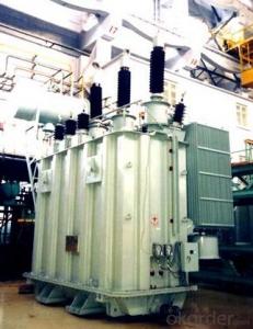

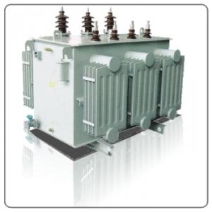
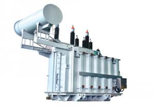
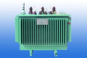
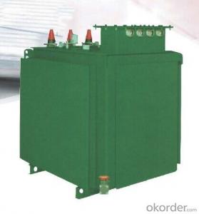
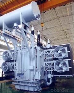
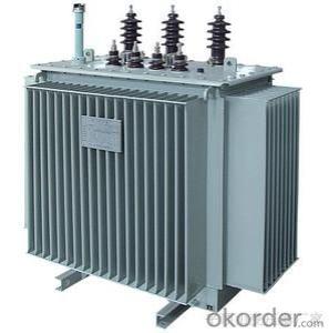
25MVA/110kV railway balance traction transformer
- Ref Price:
-

- Loading Port:
- Tianjin
- Payment Terms:
- TT OR LC
- Min Order Qty:
- 1 pc
- Supply Capability:
- 1 pc/month
OKorder Service Pledge
OKorder Financial Service
You Might Also Like


Quick Details
| Place of Origin: | HeBei | Brand Name: | CNBM | Model Number: |
|
| Usage: | Power | Phase: | Three | Coil Structure: | Toroidal |
| Coil Number: | 3 Winding | Capacity: | Rated Voltage: | 25MVA/110kV | |
| Connection Symbol: | YNd11 Dyn11 YNyn0d11 | Tank: | Cover type or Bell type | OLTC: | MR or ABB or SMS |
Packaging & Delivery
| Packaging Detail: | Mainbody --naked Disassembled parts -- crate |
| Delivery Detail: | 3 months |
Specifications
1. CESI certificate
2. High short-circuit withstand
3. Low loss, PD and noise
4. CTQC certificate
5. No leakage
Description
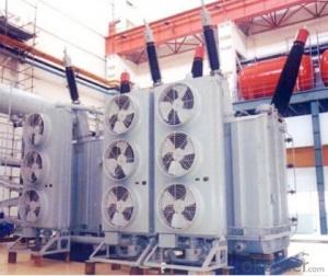
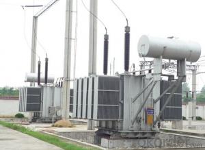
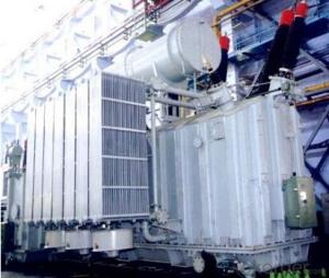
The application of the 25MVA/110kV railway balance traction transformer, and matches well with the transmission capacity of UHV lines, which has wide prospect of application. Because of its large capacity and large volume, the whole transportation weight with nitrogen is about 470-490 tons, and due to the restricted transport conditions, the transportation becomes the critical issue for application of the 25MVA/110kV railway balance traction transformer. In order to make the products applicable to any UHV substation in our country, the state grid of corporation of China set the "A study of easy-transport large capacity UHV Transformer” as a key scientific research projects, and entrusted BTW to carry out the research.
During the process of research and development, BTW adopted the advanced design technology and modular design, the transformer can be transported disassembly and with advantages of compact core and winding body, less transportation weight and low transportation cost, effectively solves the need of UHV construction in the transportation restricted areas. By using the most advanced 3D magnetic field calculation software, BTW performed detailed analysis and calculation for the magnetic flux leakage and eddy current loss of the transformer coil, iron core and oil tank steel structures. Besides, by using of the advanced electric field calculation software, BTW performed detailed analysis and calculation of main longitudinal insulation, and mastered the arrangement of the main longitudinal insulation of large capacity UHV transformer and the control of distribution of winding magnetic flux leakage. All of which make the products with low loss, low noise, small volume, strong anti short circuit ability, no local overheating and other significant advantages, and guarantee the long-term safe and stable operation.
The world's first on-site assembled large capacity UHV Transformer’s right at the first time once again filled the gap in the field of UHV transformer research after Chinese transformer industry overcame the difficulty of integral transport of the 25MVA/110kV railway balance traction transformer, which marks BTW has fully occupied the world transformer industry technical peak. The successful development of the product filled the gaps in the domestic technology and met the urgent need of UHV construction application in our country, greatly improved the technical level and manufacturing ability of BTW in terms of UHV Transformer products.
- Q: How can we figure out which side of transformer is primary which one is secondary by measuring resistance ? I know that the side where input or supply is provided called primary from where the output is collected is called secondary side in both step-up step down transformersAnd, how can we troubleshoot a bad or a good transformer by measuring its resistance on both sides i.e. primary side secondary side ?thanks
- I agree with Billruss. Some digital ohmmeters have a resolution as low as 0.01 ohm which is typically less than the resistance of most windings on small and medium size transformers. The ohmmeter is useful to identify which leads go with which windings some transformers have several windings. Typically you can connect 1 volt to 6 volts ac to one of the medium resistance windings. Then measure the voltage on each of the other windings. This determines the turns ratio on a good transformer. Applying the low voltage to a different winding will show close to the same turns ratio, unless the transformer is defective. Neil
- Q: I'm getting a transformers game and idk which one to get. Should I get Transfermors: WFC (War for cybertron) or Transfermors Dark of the moon? Which one is better?
- DOM SUCKSSSSSSSSSSSS SO MUCH!!!
- Q: Why is the transformer coil insulation?
- It is easy to understand because the transformer is used in different environments, according to different insulation level selection, can extend the life of the transformer
- Q: I'd recommend a big Transformers fan for this please. So I have a Transformers series that I'm working on for fun, and I want an awesome name for it. It has Unicron in it and the Autobots and Decepticons team up to take him down. A name for that part is Cybertron Alliance. But I also need a name for story with events that take place before that, when the Bots and Cons were at war. Please help!
- Huge transformers fan? you got me ;D Sounds pretty cool. can I read it when youre done? The Ultimate Alliance Rise of Unicron it would be great if you could add more details so I could think of more names : just give a rough outline perhaps?
- Q: does anywon kno if michael bay will bring back any robots that died from his previous movies? like jazz or bonecrusher or brawl anything like that. and i know that their making transformers 3 but does anyone know whats its going to be called or what are some new transformers? thank u for all ur answers. exept the crappy wons. il just delet thos. even tho u cant. ???
- Okay let me start off by saying i'm not a nerd i just love transformers. lol. But from what I've heard the title is Transformers: Ascendents of Cybertron. The main villian is Shockwave. Megatron, Starscream and Soundwave are the only three that have been confirmed to be in the third one as of now. For the autobots Optimus, Bumblebee, Ironhide, Ratchet, Sideswipe, and the twins who Bay said weren't coming back are coming back. New characters for autobots include a robot named Silverbolt a red ferrari, a purple car, a blue car, and an autobot scientist. Also there introducing a new team of robots that will work with the autobots called the Wreckers, three nascars. There will also be two robot assasins ( decepticons ). And as for any returning unknown but i can tell you this they have comics that take place in between the movies and there coming out with a comic series called Transformers: Nefari or something like that which takes place after the second film and somehow Ravage the dog like decepticon who was killed by Bumblebee somehow comes back to life and Alice that robot chick from college somehow comes back and was captured by sideswipe after stealing an RV and was taking to NEST for tests. Oh and one more thing. The film is supposed to start of during the days where John F. Kennedy was president and something with a decepticon on the moon happens. But the film supposely says that the decepticons had something to do with the cold war and World War II. Hoped this helps
- Q: I like to construct an autotransformer . Input voltage .240Vsingle phase. to use in a system whose operation voltage is 120v. 15 amps 1000 watts can some suggest me as to how i should proceed in calculating size of core ,winding turns, wire sizes etc , now i have 4 inches square E type transformer core . I removed all windings from it. It was used in a microwave .
- You are very much over-complicating the problem. All you need is to get an 18-volt transformer and design a 15 volt voltage regulator circuit based on it. Radio Shack has lots of books, parts, and resources to get you going. Also, check your local public or college library for electronics books. Have fun!
- Q: i have plenty of 3 phase 220 in my shop, but one of my machines requires 440 3 phase. i was going to use a 75 kva transformer with 440 primary 220 secondary in reverse to supply the machine. it is a 15 hp motor 40 amps. i figured my minimum kva requirment to be 37.5 but more cant hurt for the potential high cutting rates i may need to achieve. i simply wanted to buy the transformer, hook the 220 3 phase supply to the primary, and the output to my machine. I think this will provide me with 440 output. the motor plate says 7-1/2 hp/15- hp. 40/20 amps. Any help is welcome, i hate to buy the transformer and not have this unit work. i would change the motor wiring, but the diagram is gone, and the wires are not numbered, also i believe id have to change all the heaters, which are hard to come by, as well as various other parts in the panel. just seems the transformer is the easiest way to get this machine up and going in prouction.
- transformers can either be step up or step down, it will surely work.
- Q: I am making a small Tesla Coil, but have a question regarding the transformer. Would it work to simply wind one myself with the correct winding ratio to get the voltage I want (around 7-10kv) or is it better to stick with a commercially available transformer? (I would rather not have to buy one) Any advice for winding a transformer?
- I say buy one or find one that you can have for free. Whenever I build a Tesla Coil, I consider the transformer the first line of protection for pretty much any electronic circuitry on the same mains line because it acts to isolate the Tesla coil. I would never operate a home built transformer off of mains power. However, if your insistent on doing that, all I can do is advise you to get the resistance of your primary right, otherwise your transformer will quickly melt. An easier solution would be to find and contact neon sign businesses around your area. When they have to discard an old (but not necessarily bad) transformer, it COSTS them money because the EPA requires special handling because some can contain hazardous materials. Explain what your doing and if youre lucky, youll find a tech who is open to giving you a few of their junk stock.
- Q: I thought the movie was great, but the death of Megatron seems really rushed and just unsatisfying? Agree?
- the movies was AWSOMEEE saw it at the cinema, when i got and saw a car i had the feeling it's going to transform into a robot lol :P cant wait for the new one
Send your message to us
25MVA/110kV railway balance traction transformer
- Ref Price:
-
- Loading Port:
- Tianjin
- Payment Terms:
- TT OR LC
- Min Order Qty:
- 1 pc
- Supply Capability:
- 1 pc/month
OKorder Service Pledge
OKorder Financial Service
Similar products

Hot products

Hot Searches
Related keywords

