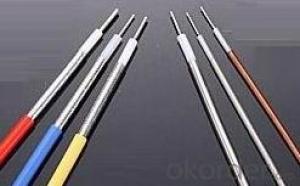


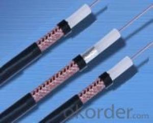
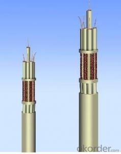
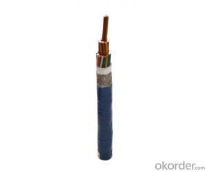
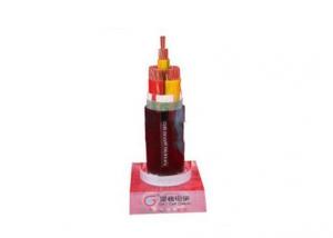
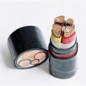
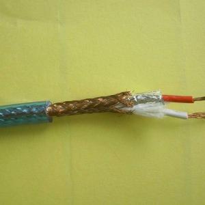
RG Series Fluoroplastic Polyethylene Insulated Coaxial Cable
- Ref Price:
-

- Loading Port:
- Shanghai
- Payment Terms:
- TT OR LC
- Min Order Qty:
- 100 m
- Supply Capability:
- 100000 m/month
OKorder Service Pledge
OKorder Financial Service
You Might Also Like
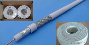
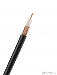
This product is based on MIL-C-17 design manufacture, mainly used for high temperature condition radio communication, radio and related electronic equipment in RF signal transmission.
Type | Inner Conductor | Insulation OD | Outer Conductor | Jacket | |||
n/mm | Outer diameter | Braided screen | Outer diameter | Nominal thickness | Outer diameter | ||
RG-178/U | 7/0.10 | 0.30 | 0.84±0.07 | Single silver Copper wire | 1.38 | 0.2 | 1.80±0.15 |
RG-179/U | 7/0.10 | 0.30 | 1.50±0.18 | Single silver Copper wire | 2.10 | 0.2 | 2.53±0.15 |
RG-180/U | 7/0.10 | 0.30 | 2.59±0.18 | Single silver Copper wire | 3.15 | 0.2 | 3.58±0.15 |
RG-316/U | 7/0.17 | 0.54 | 1.50±0.18 | Single silver Copper wire | 2.10 | 0.2 | 2.50±0.15 |
RG-302/U | 1/0.65 | 0.64 | 3.70±0.18 | Double silver Copper wire | 4.47 | 0.3 | 5.13±0.15 |
RG-303/U | 1/0.93 | 0.93 | 3.00±0.18 | Single silver Copper wire | 3.71 | 0.2 | 4.08±0.15 |
RG-304/U | 1/1.49 | 1.49 | 4.70±0.18 | Double silver Copper wire | 6.33 | 0.3 | 7.08±0.15 |
RG-393/U | 1/2.38 | 2.38 | 7.24±0.20 | Double silver Copper wire | 9.14 | 0.35 | 9.91±0.20 |
RG-400/U | 19/0.20 | 1.00 | 3.00±0.18 | Double silver Copper wire | 4.32 | 0.3 | 4.93±0.15 |
RG-404/U | 7/0.10 | 0.30 | 0.91±0.07 | Single silver Copper wire | 1.41 | 0.2 | 1.85±0.15 |
| Type | Characteristic Impedance
Ω | Insulation Compression
kV | Capacitance pF/m | Ratio % | Insulation Resistance MΩ.km | |
RG-178/U | 50±2 | 2.0 | 100 | 69.5 | 5000 | |
RG-179/U | 75±3 | 2.0 | 63 | 69.5 | 5000 | |
RG-180/U | 95±5 | 2.0 | 55 | 69.5 | 5000 | |
RG-316/U | 50±2 | 2.0 | 100 | 69.5 | 5000 | |
RG-302/U | 75±3 | 1.0 | 67 | 69.5 | 5000 | |
RG-303/U | 50±2 | 5.0 | 100 | 69.5 | 5000 | |
RG-304/U | 50±2 | 5.0 | 100 | 69.5 | 5000 | |
RG-393/U | 50±2 | 7.5 | 100 | 69.5 | 5000 | |
RG-400/U | 50±2 | 3.0 | 100 | 69.5 | 5000 | |
RG-404/U | 50±2 | 1.5 | 100 | 69.5 | 5000 |
Type | Attenuation Constants | ||||
50MHz | 100MHz | 400MHz | 1000MHz | 3000MHz | |
RG-178/U | 38.1 | 52.6 | 108.4 | 170.8 | 308.7 |
RG-179/U | 24.6 | 36.1 | 69.0 | 155.0 | 200.0 |
RG-180/U | 18.5 | 24.0 | 55.8 | 136.0 | 178.0 |
RG-316/U | 24.6 | 36.1 | 69.0 | 155.0 | 200.0 |
RG-302/U | 8.6 | 13.6 | 26.3 | 52.4 | 85.4 |
RG-303/U | 8.9 | 13.8 | 28.3 | 49.3 | 92.0 |
RG-304/U | 5.9 | 8.9 | 21.0 | 36.5 | 131.4 |
RG-393/U | 5.6 | 8.5 | 16.5 | 59.1 | 147.8 |
RG-400/U | 10.5 | 14.8 | 34.5 | 55.8 | 124.8 |
RG-404/U | 45.2 | 95.6 | 164.2 | 226.4 | 372.0 |
- Q: Hello,I recently bought a kotatsu and I really need some help. The power cable is of course Japanese... And I need some type of converter.On the part of the cable that plugs into the radiotaor it says:PSE (It's in some square box)JET MR7A 250VOn the end that plugs into the wall it says:PSE (It's in some square box)JET MR7A 125VI''m not sure if a simple small converter to let me put the Japanese cable into my wall is enough, I think I need something extra to make sure nothing goes into flames.Inside the Japanese instruction manual I found some info ... However, I'm not really sure if it is related to the power supply or not...AC100V 50-60Hz400W3.1 (Probably the length of the cable) 1.3 (Same here I think)140Wh 60 Wh55C 37CPlease help me, what should I get to be able to use the cable in Europe. Any links at all will be helpful...Thanks.
- Don't worry too much about what the cord says. Worry about the power requirements on the appliance label, and making sure you are feeding it with the voltage required, with a capacity within the range. In your instance, you will need a converter transformer that converts your outlet voltage to 100V, and has 550 or larger watt capacity.
- Q: hi, i just got a new graphics card for my PC and it needs a 6 pin power cable so i got one but i don't know where to plug it in (not on the graphics card but in the computer) can some one help me pleas.
- follow your power supply unit (PSU) main loom and try to find one that is the same on the video card if there is not one you should have at least one of those 4 pin ones it is usally white or black about 5mm thick and 25mm wide you can get adaptor plugs I had to get some for my new video card just goto to a decent computer store and they will have them I paid about $4 for each and they had 2X6pin from the one adaptor plug
- Q: I have an HP Pavilion ze5385us.... the power cable is messed up and I'd like to replace it, but the ones on the HP website are pretty expensive... I have a different computer so if I have to spend over 100 bucks then forget it. Does anyone know of a good generic brand?
- Most small repair shops sell used parts and cables.
- Q: for any SATA 2 HDD, the power connector is longer. compared to the data transfer cable. wht is it so?,-------------- ,------the first set of lines represent the power connector second; the data connection cable.
- The sata power connector provides 3.3, 5v and 12v as well as two ground connections (in between the 3.3 and 5 and 5 and 12) I believe. Anyway, for the power connectors, a single pin has a maximum rating of 1.5A or so, and so they provide three pins if a device needs needs more current.
- Q: what the size of power cable 3 core for motor 18.5 Kw with star dalta starter?
- Full load current is 32 amps,phase current is 18.4 amps Hence 3 core 15 sq.mm power cable is req.or 3 core 6 sq.mm 2 nos of cables req. to connect motor to starter.
- Q: lets say for an optical drive, the power cable has four pins. im guessing that there is power (12v?) and ground but what about the other two?im trying to plug a pair or old neon sticks into my car for accent lighting and i need to know where to put these wires at, if they are all neccessary.
- The four pin connector that is used to power PC drives supplies two different voltages: +12 volts for the motor +5 volts for the electonics The other two pins are ground pins. ________ / .............. |..1..2..3..4..| |.................| Pin Function 1 +5 V 2 Ground 3 Ground 4 +12 V
- Q: remove just this cable or use different hd and it works fine, is the hd broken or is it a power consumption by the hd issue? tryed a different psu and its the same problem, unfortunately not got another pc handy to check the hd on. Thanks In advance?
- change the hdd interface bus u may get solution otherwise replace it. .in
- Q: The power supply I have has 8 Peripheral cables. I need just a few more than that. Is there a cable splitter I can get? Or what can I do? I have the power, just need the extra connectors.
- yes,they okorder /
- Q: I am using a Peavey Windsor half-stack that I've had for a little over a year now. It's 300 watts, 120 VAC (whatever that means), and 60 Hz. I lost the power-cable so I bought a new one, but I wanted to make sure there's no risk in using it. I'm pretty sure it's safe but I'd hate to overpower it if that's possible.
- It means that it has 300 watts of power . Thats a lot of power. 120VAC means that you connect it to a regular wall plug. If you can connect it to the amp and the wall socket , you got yourself an amp.
- Q: I have a usb hub that is externally powered that stays on 24/7 even when i shut my computer off. It is buried behind by desk so removing the usb power supply manually each time is what im trying to avoid. Is there anyway i can put a switch in the power cable going to it?
- Before you attempt this, make sure you have the following items: -Wire strippers -Electrical tape -Two terminal switch -Scissors IMPORTANT! make sure that the cable is unplugged from the computer and the hub before you do this! 1st, cut the cord halfway with the scissors. Next, remove the outer wire insulation from the two new ends you just cut with the wire strippers. Now strip the small colored wires that are now exposed. Then connect the red wire from one half of the cord to a terminal on the switch. Do the same with the other red wire from the other half of the cord and connect it to the other terminal on the switch. Strip the other small wires and connect them back to their appropriate colored wire. Finally, wrap each wire individually with electrical tape, then wrap the entire gap in the cord with it. Now plug the cord in and try it out!
Send your message to us
RG Series Fluoroplastic Polyethylene Insulated Coaxial Cable
- Ref Price:
-
- Loading Port:
- Shanghai
- Payment Terms:
- TT OR LC
- Min Order Qty:
- 100 m
- Supply Capability:
- 100000 m/month
OKorder Service Pledge
OKorder Financial Service
Similar products


Hot products
Hot Searches

