

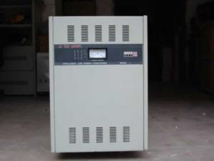
JJW SJW A.C. Precision Purity Regulated Power Supply
- Ref Price:
-

- Loading Port:
- Shanghai
- Payment Terms:
- TT or LC
- Min Order Qty:
- -
- Supply Capability:
- 10000pcs pc/month
OKorder Service Pledge
OKorder Financial Service
You Might Also Like


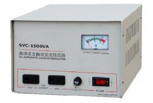
1. Product Description:
It often happens that the electrical equipment are damaged because of lack of power. The experts of power point out most 80% malfunctions of computer are caused by A.C. power supply directly or indirectly. So as to ensure the safe operation of electrical equipment, the power supply must be improved. Our products fulfill the requirements in such places for his spurious characteristic. Our products are suitable for the following fields: science department, university, corporation, hospital, broadcasting station, communication equipment, traffic system, test equipment and all automatic production equipment.
2. Product Characteristic:
A.C. Precision purity regulated power supply is our new, high characteristic electronic A.C. regulated equipment as KUPA doctor’s theory, combining Asymmetrical Digital Subscriber Loop colander net, which integrates multi-functions such as purity regulation and anti-disturbance. They are of wide range in regulation, fast speed in response, high precision in regulation etc.,to refrain all kinds of noise from power net and disturbance from peak. They are your first choice among of A.C. regulated power supply at present, which are 614 series electronic A.C. regulated power supply and ideal substitution regulated power supply.
3.Specification:
Single phase:170-270V Three phases:310-450V
Range of input regulation:
Single phase:185-250V, output:220±5%
Three phases:330-450V, output:380±0.5%
Input frequency:50Hz±5%
Alarm value of output voltage
Single phase:output higher than 242V or lower than 198V
Three phases:output higher than 418V or lower than 342V
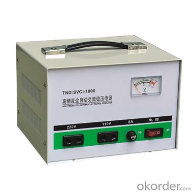
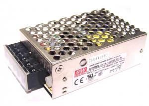
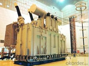
4. Reference Picture:


- Q: High school physics, according to the transformer U1 / U2 = N1 / N2 Can make a large voltage into a small voltage, but the small voltage can become a large voltage? Need no conditions? Can the transformer be used only for alternating current? I am now only high school physical level, answer not too esoteric or too professional! Thank you !!
- Transformer is divided into two kinds! One is the booster, the other is the buck! It is by changing the transformer coil winding to determine the effect of its pressure!
- Q: How much capacity the transformer has
- For power transformers, there are 10 20 30 40 50 63 80 100 125 160 200 250 315 400 500 630 800 1000 1250 1600 2000 2500 3150 4000 5000 6300, etc. kVA.
- Q: I saw the first one, thought it was great, and the second one was even better. But are they planning on making another one? If so, do you know what its going to be about?IMO, i think it should be about Unicron, yes that would be kool haha.
- hey, they announced transformers 3 before transformers 2 came to theatres
- Q: I know there has been plenty of Transformers anime over the years, but is there any Transformers manga?
- Have you tried googling it? Good luck! I remember seeing Transformers in JPN since I was little I think they've been around since the 80s. At least I've seen the toys in JPN since then.
- Q: Do you think if I asked this. which I am maybe people will pick Transformers because more Americans watch Trans instead of Gundam but if people watched both, would they still pick Transformers?
- Dude, Gundam. Always. Transformers Armada was funny but the movies and tv shows never really seemed that good. Its just because it has megan fox in the movie. That's why so many people think Transformers are cool. Gundam is the ultimate. Especially Gundam Seed and Wing.
- Q: I really want to know what a transformer is, how it works, and why it works. I really want an answer that goes down the the atomic scale. I really want analogies. And please don't copy and paste stuff from websites. Please don't worry about getting second comment. The most scientific and well explained answer gets best answer.
- I know this isn't what you asked for, but it gives a much better answer than I'm willing to type.
- Q: I'm 13 and I love the Transformers movie, TF Animated and TF Armadaactually, those are the only ones I HAVE seen so farI'm just wondering where to start with attempting to watch them all? And in what order? Or, doesn't it matter? I suppose it does with G1 and 2Where on the internet can I watch them? Any recommendations?Please answer! I really want to have seen every one!
- not okorder
- Q: I don't know much about Transformers but the movie looks great. So how many are there, and name them. Are they good or bad?
- Autobots (Good) Optimus Prime Ironhide Bumblebee Jazz Ratchet Decepticons (Bad) Megatron Blackout Starscream Barricade Scorponok Frenzy Bonecrusher Brawl
- Q: Hi! Anything you wanna say about transformers, leave here!
- Transformers are cool!!!!!!! Transformers movie freaken awesome!!!!!! Transformers Animated its OK could be better, but still OK. Also can't wait until the next Transformers movie to come out!!!!!!!!!!!
- Q: im building a step up transformer and im wondering if a 10:130 turn ratio would give me the same results a 100:1300 turn ratio. my specific questions are:1) Would i get the same power boost?2) If not, would it be similar or close to it?3) If not, why not?
- It will give you the same open-circuit voltage ratio. Winding more turns on the cores will increase your inductances on both sides. That reduces the open-circuit current on the driving side. More wire resistance will result in more resistive loss when operating with a load.
Send your message to us
JJW SJW A.C. Precision Purity Regulated Power Supply
- Ref Price:
-
- Loading Port:
- Shanghai
- Payment Terms:
- TT or LC
- Min Order Qty:
- -
- Supply Capability:
- 10000pcs pc/month
OKorder Service Pledge
OKorder Financial Service
Similar products
Hot products


Hot Searches

