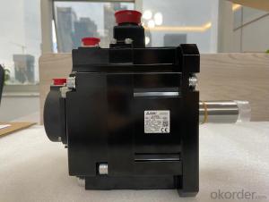


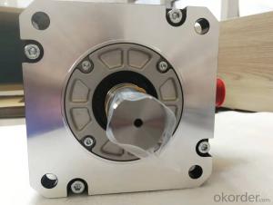
Intellectualization HG-SR202BJ Motor For Semiconductor Manufacturing
- Ref Price:
-

- Loading Port:
- Shanghai
- Payment Terms:
- TT OR LC
- Min Order Qty:
- 1 kg
- Supply Capability:
- 2000 kg/month
OKorder Service Pledge
OKorder Financial Service
You Might Also Like


Motor series: low inertia, medium power. Rated output power: 30.0kw. Rated
speed: 1500r / min with brake or not: No. Shaft end: Standard (straight shaft).
Voltage: 400V type.
Protection level: IP65 (p67) hg-sr202bj basic knowledge.
Features: low inertia, from low speed to high speed, three modes can be
selected, suitable for different application ranges. As a standard production
port, hg-sr202bj is installed with 30kW or higher dry flange and feet
Application examples: basic knowledge of injection molding machine,
semiconductor manufacturing installation, large transmission machinery hg-
sr202bj. High resolution encoder 131072p / rev (17 bits).
High resolution encoder is included to ensure excellent performance and
stability at low speed.
All motors are the same size as the previous products and the wiring is
compatible. Motor series: low inertia, low power. Rated output power: 0.75KW.
Rated speed: 3000r / min. with brake or not: attached.
Shaft end: keyway (slotted position).
Protection level: IP55, excluding the shaft threading part and the basic
knowledge of connector hg-sr202bj. Features: low inertia, suitable for high
frequency operation.
Application examples: inserter, assembly machinery. Motor series: medium
inertia, medium capacity. Use serial pair / incremental encoder. Rated output
power: 3.0kw. Rated speed: 1000rpm. With or without band brake: No. Shaft end:
straight shaft.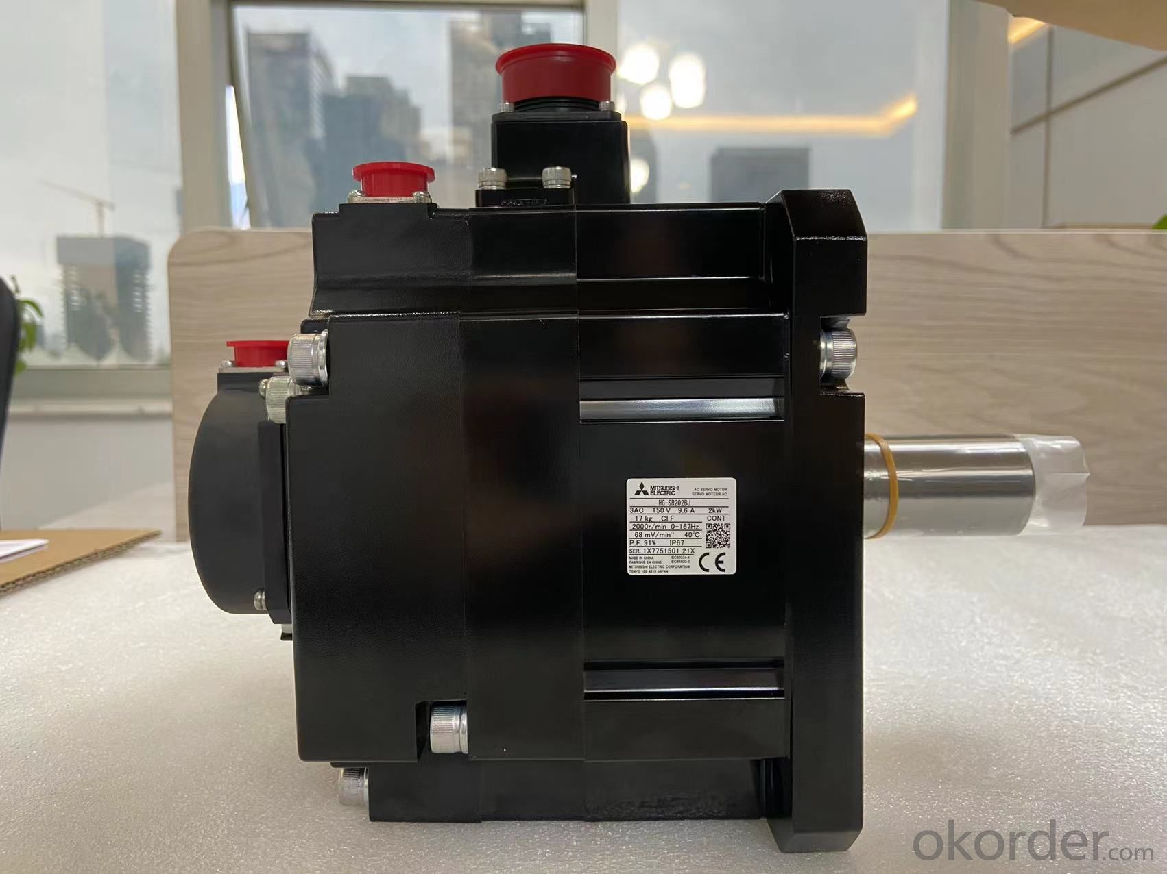
The stator structure of AC servo motor is basically similar to that of
capacitor split phase single-phase asynchronous motor hg-sr202bj (type
selection data). The stator is equipped with two windings whose positions are
90 ° different from each other. One is the excitation winding RF, which is
always connected to the AC voltage UF, and the other is the control winding L,
which is connected to the control signal voltage UC.
Therefore, AC servo motor is also called two servo motors. Motor series: medium
inertia, medium power. Rated output power: 3.5kw rated speed: 2000r / min.
With brake or not: hg-sr202bj (model selection data) is attached. Shaft end:
Standard (straight shaft). Protection level: IP65 (IP67).
Features: there are three modes of medium inertia from low speed to high speed,
which are suitable for different application ranges. Application examples:
transmission machinery, robot, X-Y worktable.
High resolution encoder 131072p / rev (17 bit) hg-sr202bj (selection data).
High resolution encoder is included to ensure excellent performance and
stability at low speed.
All motors are the same size as the previous products and the wiring is
compatible. Motor series: low inertia, medium power. Rated output power: 6.0kw.
Rated speed: 1000r / min. with brake or not: attached. Shaft end: Standard
(straight shaft). Protection level: IP65 (IP67)
Features: low inertia, from low speed to high speed, three modes can be
selected, suitable for different application ranges hg-sr202bj selection
manual. As a standard production port, 30kW or higher power is suitable for dry
process blue plate (type) installation and foot installation. Basic knowledge
of hg-sr202bj. Application examples: injection molding machine, semiconductor
manufacturing device, large conveying machinery. High resolution encoder
131072p / rev (17 bits).
High resolution encoder is included to ensure excellent performance and
stability at low speed. All motors are the same size as the previous products
and the wiring is compatible.
- Q: can someone please give me transformers war for cybertron ps3 controlls
- Don't know
- Q: I need this Radio Shack transformer to provide power to a HO scale model train board lighting system. This transformer will be connected to a brightness control system and then the brightness control system will be connected to building lights and street lights. I have been told this issue is a safety and Electrical Code concern?
- Tying the neutral to ground gives the system a reference point. Your system will then be protected against earth faults which would allow circuit fuses to blow to protect each sub-circuit should an earth fault develop. Without the neutral earth connection an earth fault on a given sub circuit would not result in a fuse blowing / breaker tripping thereby potentially causing associated metalwork to reach dangerously high potential and possible danger of electric shock should a person happen to touch the live metalwork and live parts at the same time.
- Q: Power transformer parameters
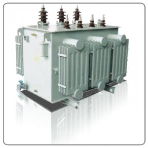
- First, the transformer technical parameters The main technical parameters of the power transformer are: rated power, rated voltage and voltage ratio, rated frequency, operating temperature class, temperature rise, voltage adjustment Rate, insulation performance and moisture resistance, the main technical parameters for the general low-frequency transformer parameters are: transformer ratio, frequency characteristics, nonlinear distortion, magnetic shielding and electrostatic shielding, efficiency and so on. A. Voltage ratio: Transformer two sets of coil turns are N1 and N2, N1 for the primary, N2 for the secondary. In the primary coil plus an AC voltage, the secondary coil will produce both ends of the induced electromotive force. When N2> N1, its induction The electromotive force is higher than the primary voltage. This transformer is called a step-up transformer: when N2 <N1, its induced electromotive force is lower than the primary voltage, which is called a descending transformer. Primary secondary voltage and coil The number of the following relationship: where n is called the voltage ratio (turns ratio). When n <1, then N1> N2, V1> V2, the transformer is a step-down transformer.
- Q: I went to go see transformers yesterday and one of the previews shows a bunch of people at a party with someone videotaping the party. Then there are explosions in the distance and at the end the head of the statue of liberty lands in the street. They don't say what the name of the movie is but it has a january of 2008 release date. Does anyone know the name of this movie?
- I thought I saw, in quotes, that it was called Bad Robot. Maybe it is/was a working title.
- Q: Can an efficient transformer step up energy?
- Yeah, they can do both, but has nothing to do with efficient. If you're asking if they can efficiently do it, that's in the eye of the beholder. In my eyes they can't. Oh, and when you are saying energy I suspect you mean voltage?
- Q: Transformer rated capacity 500 / 750KVA (AN / AF) What does it mean?
- Air cooling can improve so much no sure no problem, and now a lot of transformer air cooling and self cooling ratio is 100: 80, 100: 70, there are 100: 60.
- Q: If a transformer is rated for a maximum winding current of 10A, would it be permissible to operate it with 10A of input current when the secondary voltage to the load is 40V? Can you explain to me why?The information on the auto transformer plate wasInput 240V/ 50/60 cy 3HPoutput 0-240/280V 20 ampsThe parallel load resistance is 34.5 ohms
- At 40 V and 10 A the VA is 400 on the secondary side. At 240 V on the primary side the current is 400/240 which is 1.66 A. If the load on the secondary side is 34.5 ohms at 40 V then the secondary current is 40/34.5 1.16 A and the the VA on the secondary side is 40 x 1.16 46.4. T he VA on the primary side then is 46.4 and the primary current is then 46.4/240 0.19 A. 3 hp is 746 x 3 Watts 2238 W and its rated current on the primary side is 2238/240 9.325 A. In other words the VA loaded on to the secondary side is the same VA (more or less) as that on the primary side.
- Q: By applying ohms law in the secondary circuit, IV(stepped up)/R , a stepped up voltage would result in an increase of current, i am aware that the step up transformer steps down current, but it is the secondary circuit that determines the current draws (ohm's law), and the primary current is multiples of itSo ?!!!!
- Here are some basic equations for transformer. V-high / V-low N-high / N-low Eq. 1 I-low / I-high N-high / N-low Eq. 2 where, V-high voltage at high voltage side V-low voltage at low voltage side I-high current at high voltage side I-low current at low voltage side N-high number of winding turns at high side N-low number of winding turns at low side Eq. 2 above could be written as I-high (N-low / N-high)I-low substitute Eq. 1 I-high (V-low / V-high)I-low Eq. 3 Let us have an example to give a good answer to your question. Consider a 30 MVA, 13.8-138 kV, 3-phase step up transformer. The 13.8 kV is at the generator side and the 138 kV is at the transmission side. Low side current is I-low 30,000,000 / 1.732(13,800) 1255 A High side current is I-high 30,000,000 / 1.732(138,000) 125.5 A it shows that I-high is less than I-low. Also, using Eq. 3 to further confirm result, we have I-high (V-low / V-high)I-low I-high (13,800 / 138,000) 1,255 I-high 125.5 A
- Q: How does a step down transformer decrease the output voltage but increases the output current? And how does the step up transformer does the opposite thing?
- that one you have to ask the energy saver I think they have the solution.
- Q: !!! I took a cardboard cylinder from a used firework, dug out all the crap, wrapped 160 turns of tinned copper wire on the outside tight and evenly so it is a beautiful solenoid, held it in place with 2 rubber bands. That was the secondary. Then I wrapped an insulated steel wire around a screwdriver shaft 10 times, stretched it out a little inserted a chopstick into this primary and inserted the chopstick into the firework. I then held it all in place with tissue paper and tape and wired the primary up to a pulsed DC circuit which was made of 3.0 volts wired to a steel file which I rubbed the electrode across. The secondary was wired to a current detector but I got no signal! Why is there zero inductance in my transformer and why is there no current at all? It can't even light up a small lightbulb!!
- There is a little more to transformer design than this. Your secondary should have used insulated wire (varnished or enamel would do) as even one turn shorting will give problems. Also, you need to consider the magnetic circuit formed by the steel core. It is usual to use soft iron for this as otherwise the hysteresis will be too large. The entire magnetic flux needs to be concentrated into the secondary so you will need to consider the magnetic path. The transformer is essentially just two (or more) inductors, sharing a common magnetic path. Any two inductors placed reasonably close to each other will work as a transformer, and the more closely they are coupled magnetically, the more efficient they become.
Send your message to us
Intellectualization HG-SR202BJ Motor For Semiconductor Manufacturing
- Ref Price:
-
- Loading Port:
- Shanghai
- Payment Terms:
- TT OR LC
- Min Order Qty:
- 1 kg
- Supply Capability:
- 2000 kg/month
OKorder Service Pledge
OKorder Financial Service
Similar products
Hot products


Hot Searches

