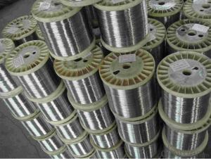
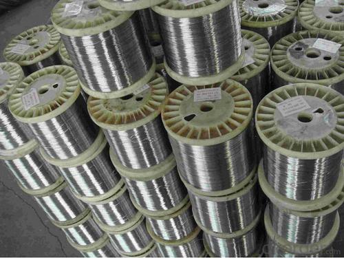
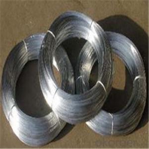
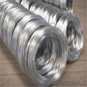
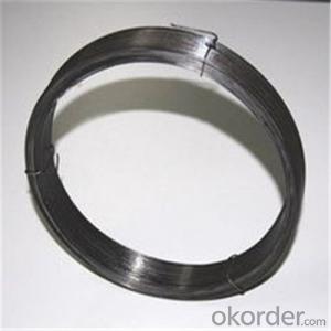
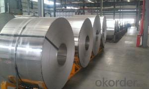
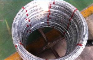
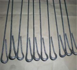
inconel 625 , incoloy 600,625,718,725,800,825 wire coil
- Ref Price:
-

- Loading Port:
- China Main Port
- Payment Terms:
- TT OR LC
- Min Order Qty:
- -
- Supply Capability:
- -
OKorder Service Pledge
OKorder Financial Service
You Might Also Like


Specifications
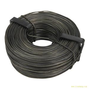
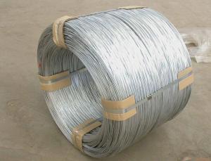
Incoloy 625 wire coilIncoloy 625 bar rod
Specification: Min 0.02mm
Best quality and lowest price
Special spec wire ordered
Specifications
Incoloy 625
1)Forms: Wires, Bars, Strip/Coil, Plate. forging
2)ISO Certification
3)High quality with good performance
Grade
GH1140,GH2132,GH3128,GH3030,GH3044,GH4145,GH4146,GH4169.
NS111,NS112,NS113,NS142,NS143,NS312,NS313,NS315,NS321,NS322
NS333,NS334;
NS336;1J30,1J36,1J50,2J22,2J85,3J01,3J09,3J21,3J40,3J53,4J28,4J29,
4J36,4J42,4J50,6J20,6J22;
Iconel625,Inconel625LCF,Inconel690,Inconel600,Inconel601,Inconel617,
Inconel686,Inconel718,Inconel718SPF,Inconel706,Inconel725,Inconel751,
Inconel783,inconel X-750
Incoloy800,Incoloy800H,Incoloy800HT,Incoloy801,Incoloy825,Incoloy903,
Incoloy907,Incoloy925,Incoloy926,Incoloy25-6Mo,IncoloyA-286
HastelloyB,hastelloyB-2,hastelloyB-3,hastelloyC,hastelloyC-4,hastelloyC-22,
HastelloyC-276,hastelloy C-2000,hastelloyG-3,hastelloyG30, hastelloyX,
HastelloyHX
Monel400,MonelR-405,MonelK-500
- Q: How is the line differ from a neutral and ground wires in a three prong plug?
- the bare wire is the ground and goes to the green lug == the black wire goes in the brass screw/lug=== and the white wire then goes in the silver/aluminum looking screw/lug === the purpose of the ground is to act as a safety net to prevent shocks and c
- Q: Hi,I have an issue with wiring in house. This is in Paris, France. I will share a foto so you can have a clearer picture what my question is.
- It's not just your oven that makes a difference, but the year your oven was manufactured in AND the country it was manufactured in that makes a difference. It was easy to identify your supply wires as Brown = live wire; Blue = return (neutral) wire; green/yellow = earth ground, and this is single phase wiring. There would be an orange wire for 3 phase... ...but the oven wiring conforms to a different standard of gray - white -red where red is possibly the ground line, while the other two are your live and return wires, with the gray likely to be the return wire....BUT...in some time periods, the red wire was the live wire. Your best bet is to test the oven wiring out with a multi-meter and look at what color of wire is connected to where. The earth ground should be connected to the oven's cabinetry; the live wire would be wired to the oven's internal fuse or circuit breaker, and then wired to the business end of the heater elements, timers, etc. The return wire would be connected to the other side of the elements and timers. Your most reliable way to address this is to consult a professional. That second link I posted has both old and new French wiring standards, and neither match your oven. And if your oven isn't manufactured in France, you have yet another level of wiring code to unscramble.
- Q: let me start off with I am not an electrician I just do basic stuff for side work I came in the project at the end. The lady wanted me to wire in 6 receptacles, a light switch and light fixture all on one circuit. everything is good except for the receptacle at the start of the circuit it has the lead/ hot coming in the power to the other receptacles going out and the power to the light going out (3 groups, 9 wires total). normally I would have used a junction box but I didn't pull the wire. How can I wire this. Would a 15 amp receptacle work?
- A 15 Amp receptacle will work, of course, but the receptacle box is most likely already overfilled. So in order to keep the wire count down, your best way to go is to buy a receptacle that uses screw down connector tabs. (NOT the kind that you have to put the wire under the screw, but the kind that you insert the wire into the back and then turn the screw down to clamp onto it!) The receptacle is a little more money but it would be worth the expense to make this hook up work. Hot wire (Black): Connect all three black wires to the back of the receptacle on the brass colored screws. Common wire (White): Connect all three white wires to the back of the receptacle on the silver colored screw. Ground: make a short pigtail of bare copper wire (about 6 or 7 inches long). Then connect the pigtail to the other 3 bare copper ground wires using a wire nut. Then connect the other end of the pigtail to the grounding connection of the receptacle. MAKE SURE THE POWER IS OFF WHEN YOU DO ALL OF THIS SO THAT YOU CAN LIVE TO TELL THE TALE! :-)
- Q: I recently took out my old ceiling fan, and now there is a Black, Red, And White Wire hanging from the ceiling, I bought a track light that has a box with a Green, White, and Black wire in it. Which wires am i supposed to connect,It's for the light Switch, and I'm not sure when the house was built, its a Reading, PA Row house.
- It looks like you had a fan and a light, with separate wall switch controls. The black was the fan and the red was the light (or vice versa) and the neutral for both. Connect the black to black, white to white and cap off the red one and turn on the switch. If the light doesn't work, switch it off again (at the breaker, silly), connect the red ceiling wire to the black wire of the light, cap off the ceiling black wire and try again.
- Q: A potential difference of 13 V is found to produce a current of 0.37 A in a 3.1 m length of wire with a uniform radius of 0.42 cm.(a) What is the resistance of the wire? (b) What is the resistivity of the wire? Please show work.
- Voltage (Volts) = Current (Amps) times Resistance (Ohms) or V=IxR = R = V/I = 13/0.37 = 35.14 Ohms Resistance = Resistivity * Length/Area The longer the wire is, the more resistance it has. The larger the crossectional area of the wire (pi times radius^2), the less resistance it has Longer wires have more resistance, thicker wires have less 35.14 = Resistivity * 3.1/pi*0.0042^2 Resistivity = 35.14*pi*0.0042^2/3.1 = 6.281 x 10^-4
- Q: i got a fi bl 15dual 2 subwoofer. im wiring it down to 1 ohm.now for the problem. lets say im wiring the positive terminals together. am i suppose to wire it all with positive wire or can i also use negative copper wire? i used two positive wires and one negative wire to hook up the three positive terminals. is this bad? do i need to make all of them positive silver wires?
- however way tou ire them as long as they're placed into the comparable amp they each get that plenty output. So 2 subs @ a million ohms is 1000w rms ea and a couple of subs @ 2 ohms get 750w rms ea
- Q: thin wire to make fishing tackle that sharks cannot bite
- I okorder /
- Q: I currently have a ceiling fan wired to a dimmer wall switch that controls the fan and the light, not good I know. I would like to set up the dimmer switch where it controls the light only and then i can use the fan pull switch for the fan. but i am not sure how to wire this with my current wires. In the wall box where the dimmer switch is I have two sets of wires coming from two different locations. one set has a black, red, white, and green. the other location has black, white and copper. currently the green and copper are connected and capped, the two whites are connected together and capped, two blacks are and connected to the black wire coming from the dimmer and the red is connected to the other black wire from the dimmer. how would I wire the dimmer switch to only control the light and not the fan? I want to make sure i do this safely.any assistance is greatly appreciated.
- Ok, leave the copper and green wires alone as well as the white wires. Now the red and black coming from the same set should be your fan/light switch legs with red being light and black for fan itself. You may have to go into the fan ceiling box itself as it sounds the fan and light kit are connected to red wire in ceiling box especiallly if dimmer switch is controlling both. The other blacks are power legs. If both wires from fan/light are tied in with red wire, seperate them and connect the blue wire from light kit to red and cap off. With switch off, connect black wire from fan to those black wires that are capped off in box. If this isnt right connections, contact me via my email address on profile
- Q: hey i have a 2005 toyota corolla soprt. i need help finding the remote wire, and some colors arent even on the diagram. please help i dont wanna have to buy another alternator and battery like i already have!thanks!
- Look for the gray wire in the harness. It would be much easier if you bought a wiring harness for $10 to $15. It avoids you having to cut up your vehicles existing wiring. 2005 Toyota Corolla Radio Wiring Radio Constant 12V+ Wire: Blue/White Radio Switched 12V+ Wire: Gray Radio Ground Wire: Brown Radio Illumination Wire: Green Power Antenna Wire: Black Front Speaker Size: n/a Front Speaker Location: n/a Left Front Speaker Wire (+): Pink Left Front Speaker Wire (-): Purple Right Front Speaker Wire (+): Light Green Right Front Speaker Wire (-): Blue Rear Speaker Size: n/a Rear Speaker Location: n/a Left Rear Speaker Wire (+): Black Left Rear Speaker Wire (-): Yellow Right Rear Speaker Wire (+): Red Right Rear Speaker Wire (-): White
- Q: i need to know how much wire size i have to put for 380 volts supply
- Wire size is a function of current, not voltage. So, how much current is your load going to draw.
Send your message to us
inconel 625 , incoloy 600,625,718,725,800,825 wire coil
- Ref Price:
-
- Loading Port:
- China Main Port
- Payment Terms:
- TT OR LC
- Min Order Qty:
- -
- Supply Capability:
- -
OKorder Service Pledge
OKorder Financial Service
Similar products

Hot products


Hot Searches

