


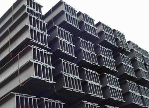
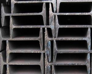
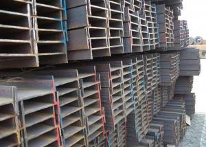
HR Steel I Beams with High Quality for Sale
- Ref Price:
-

- Loading Port:
- China main port
- Payment Terms:
- TT or LC
- Min Order Qty:
- 25 m.t.
- Supply Capability:
- 100000 m.t./month
OKorder Service Pledge
OKorder Financial Service
You Might Also Like
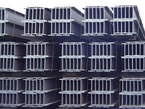
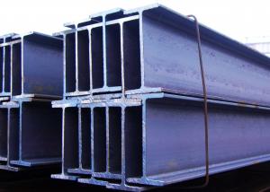
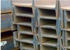

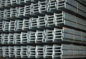
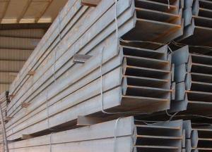
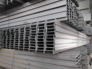
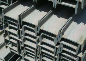
Product Description:
Production Standard: GB Standard, EN10025, DIN, JIS, etc.
Material of Steel I-Beam: Q235,SS400,A36,ST37-2,S235JR
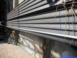
Length: 5.8M, 6M, 9M, 12M or as the requriements of the clients
Sizes: 80MM-270MM
Section | Standard Sectional Dimensions(mm) | ||||
h | b | s | t | Mass Kg/m | |
IPE80 | 80 | 46 | 3.80 | 5.20 | 6.00 |
IPE100 | 100 | 55 | 4.10 | 5.70 | 8.10 |
IPE120 | 120 | 64 | 4.80 | 6.30 | 10.40 |
IPE140 | 140 | 73 | 4.70 | 6.90 | 12.90 |
IPE160 | 160 | 82 | 5.00 | 7.40 | 15.80 |
IPE180 | 180 | 91 | 5.30 | 8.00 | 18.80 |
IPE200 | 200 | 100 | 5.60 | 8.50 | 22.40 |
IPE220 | 220 | 110 | 5.90 | 9.20 | 26.20 |
IPE240 | 240 | 120 | 6.20 | 9.80 | 30.70 |
IPE270 | 270 | 135 | 6.60 | 10.20 | 36.10 |
IPEAA80 | 80 | 46 | 3.20 | 4.20 | 4.95 |
IPEAA100 | 100 | 55 | 3.60 | 4.50 | 6.72 |
IPEAA120 | 120 | 64 | 3.80 | 4.80 | 8.36 |
IPEAA140 | 140 | 73 | 3.80 | 5.20 | 10.05 |
IPEAA160 | 160 | 82 | 4.00 | 5.60 | 12.31 |
IPEAA180 | 180 | 91 | 4.30 | 6.50 | 15.40 |
IPEAA200 | 200 | 100 | 4.50 | 6.70 | 17.95 |
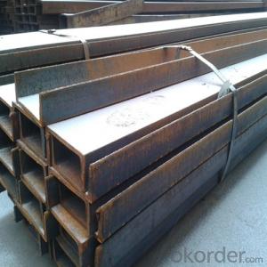
Usages:
According to the needs of different structures, steel I-beam can compose to different force support component, and also can be the connections between components. They are widely used in various building structures and engineering structures such as roof beams, bridges, transmission towers, hoisting machinery and transport machinery, ships, industrial furnaces, reaction tower, container frame and warehouse etc.
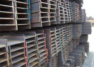
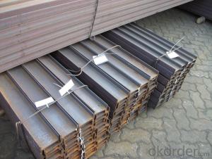
Packaging & Delivery :
1. Packing: it is nude packed in bundles by steel wire rod
2. Bundle weight: not more than 3.5MT for bulk vessel; less than 3 MT for container load
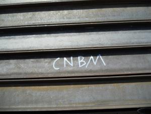
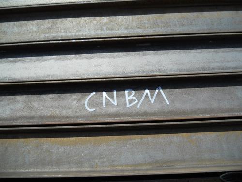
3. Marks:
Color marking: There will be color marking on both end of the bundle for the cargo delivered by bulk vessel. That makes it easily to distinguish at the destination port.
Tag mark: there will be tag mark tied up on the bundles. The information usually including supplier logo and name, product name, made in China, shipping marks and other information request by the customer.
If loading by container the marking is not needed, but we will prepare it as customer request.
4. Transportation: the goods are delivered by truck from mill to loading port, the maximum quantity can be loaded is around 40MTs by each truck. If the order quantity cannot reach the full truck loaded, the transportation cost per ton will be little higher than full load.
5. Delivered by container or bulk vessel
6. Delivery time: All the structural steel I beams will be at the port of the shipment within 45 days after receiving the L/C at sight ot the advance pyment.
7. Payment: L/C at sight; 30% advance payment before production, 70% before shipment by T/T, etc.
Production flow:
Material prepare (billet) —heat up—rough rolling—precision rolling—cooling—packing—storage and transportation
FAQ:
Q1: Why buy Materials & Equipment from OKorder.com?
A1: All products offered byOKorder.com are carefully selected from China's most reliable manufacturing enterprises. Through its ISO certifications, OKorder.com adheres to the highest standards and a commitment to supply chain safety and customer satisfaction.
Q2: How do we guarantee the quality of our products?
A2: We have established an advanced quality management system which conducts strict quality tests at every step, from raw materials to the final product. At the same time, we provide extensive follow-up service assurances as required.
Q3: How soon can we receive the product after purchase?
A3: Within three days of placing an order, we will begin production. The specific shipping date is dependent upon international and government factors, but is typically 7 to 10 workdays.
Images:


- Q: Standard for welding quality of I-beam
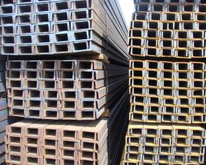
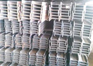
- I-beam is mainly divided into ordinary I-beam, light I-beam and H steel three.Ordinary I-beam, light I-beam flange is variable cross-section, depending on the thickness of the web, the external thin; H steel: HW, HM, HN, HEA, HEB, HEM and so on, the flange of I-beam is a uniform sectionOrdinary I-beam, lightweight I-beam has formed the national standard, the common 10# I-beam is equivalent to the Internet I100 (such as 10# also channel equivalent channel (U100) for the implementation of the standards of different countries, which have subtle differences in their specifications)H type I-beam is also called wide flange I-beam, HW, HM, HN originated from European standards, HEB is the German standard of I-beam, of which HW, HN I-beam has been widely used in our country and production. HEA HEB HEM will be seen on many German designs and is hard to buy on the domestic market. In the domestic steel structure engineering, if the quantity is few, then may use the specification steel plate to carry on the welding splicing. In the case of large quantities, it is usually considered to use mechanical properties comparable to those of HW and HN steel.
- Q: What is the difference between GB and non - marking of I-beam?
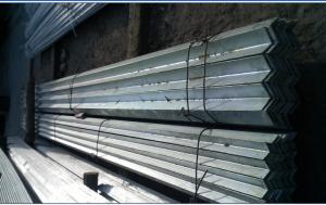
- Nonstandard is the product that does not produce according to national standard. For example, the national standard angle, is expressly thick, but some will be used when the thin iron, the market also sells, it is non-standard products.
- Q: How do steel I-beams perform in high-humidity environments?
- Due to their inherent resistance to moisture, steel I-beams perform well in high-humidity environments. Typically, the steel used in I-beams is coated with protective finishes like galvanization or paint. These finishes act as barriers to prevent moisture penetration and direct contact with water or humidity, thus preventing corrosion. Moreover, steel is a non-porous material, unlike wood or other organic materials. This non-porous characteristic makes steel I-beams less prone to swelling, warping, or rotting that can occur in high-humidity conditions. However, in extremely corrosive environments such as coastal areas with high salt content in the air, additional precautions may be necessary. In such cases, stainless steel or other corrosion-resistant alloys are commonly utilized to ensure the durability and performance of the I-beams. All in all, steel I-beams are a reliable choice for high-humidity environments. They offer strength, durability, and resistance to moisture-related issues.
- Q: Can steel I-beams be used for industrial structures?
- Yes, steel I-beams are commonly used for industrial structures due to their high strength-to-weight ratio, durability, and ability to withstand heavy loads.
- Q: Does the welding of I-beam affect its structure after welding?
- It can be splicedBut both the web and the upper and lower panels should be welded and strengthened
- Q: What does "I-beam 125A" mean?
- The same height of the I-beam, if there are several different leg width and waist thickness, need to add a, B, C on the right side of the model to distinguish, such as 32a, 32B, 32c and so on.
- Q: What are the common accessories used with steel I-beams, such as brackets and connectors?
- Common accessories used with steel I-beams include brackets and connectors. These accessories are essential for the proper installation and support of I-beams in various construction applications. Brackets are commonly used to connect I-beams to other structural components, such as columns or beams. They provide additional stability and strength by securely holding the I-beams in place. Brackets can be either welded or bolted onto I-beams, depending on the specific application and structural requirements. Connectors are another important accessory used with steel I-beams. They are designed to join multiple I-beams together, creating longer spans or supporting complex structural configurations. Connectors can be in the form of plates, cleats, or clips, and they are typically fastened with bolts or welding. These connectors help distribute the load evenly across multiple I-beams, ensuring structural integrity and preventing any potential failures. Other common accessories used with steel I-beams may include end plates, which are used to cap the ends of the I-beams for added protection and reinforcement. Additionally, various types of fasteners, such as bolts and nuts, are used to secure the brackets, connectors, and other accessories to the I-beams. These fasteners play a crucial role in maintaining the structural integrity of the entire system. It is important to note that the specific accessories used with steel I-beams may vary depending on the application, load requirements, and design specifications. Consulting with a structural engineer or construction professional is recommended to ensure the proper selection and installation of accessories for steel I-beams in any given project.
- Q: Can steel I-beams be used for commercial office buildings?
- Indeed, it is common to utilize steel I-beams during the construction of commercial office buildings. These I-beams serve to offer structural support and possess the capability to withstand substantial loads, rendering them exceptionally suitable for the creation of expansive, multi-level structures. Their impressive attributes include remarkable strength, durability, and fire resistance, thus contributing to their widespread preference in commercial construction ventures. Moreover, steel I-beams can be readily tailored and manufactured to meet the precise design specifications of an office building.
- Q: Are steel I-beams suitable for industrial applications?
- Steel I-beams are an excellent choice for industrial applications. They possess several qualities that make them ideal for use in various industrial settings. Firstly, steel is incredibly strong and durable, capable of withstanding heavy loads and high impact forces. This strength ensures the structural integrity of industrial buildings and equipment, making steel I-beams essential for supporting heavy machinery, bridges, and other industrial structures. Additionally, steel I-beams have excellent resistance to fire, corrosion, and extreme weather conditions. This makes them highly reliable and long-lasting, reducing the need for frequent maintenance and replacement. Steel I-beams can withstand harsh industrial environments, including exposure to chemicals, moisture, and temperature fluctuations, without compromising their strength or stability. Moreover, steel I-beams offer versatility and can be customized to meet specific industrial requirements. They can be fabricated in various sizes, shapes, and lengths, allowing for efficient and precise construction. This versatility enables engineers and architects to design and build industrial structures with maximum efficiency and functionality. Furthermore, steel I-beams are cost-effective in the long run. Although their initial cost may be higher compared to other materials, their durability and low maintenance requirements result in substantial savings over time. Additionally, steel is a sustainable and recyclable material, providing environmental benefits. In conclusion, steel I-beams are highly suitable for industrial applications due to their strength, durability, resistance to fire and corrosion, versatility, and cost-effectiveness. Their ability to support heavy loads and withstand harsh industrial environments makes them an essential component in various industrial settings.
- Q: Can steel I-beams be used in retail or commercial building renovation projects?
- Certainly, steel I-beams are a viable option for retail or commercial building renovation endeavors. Their strength and durability have made them a staple in the construction field. With their exceptional load-bearing capacity, they are well-suited for supporting heavy loads in both new construction and renovation undertakings. When it comes to retail or commercial building renovation projects, steel I-beams can serve a multitude of purposes. They can reinforce or replace existing structural components, offer additional support for new expansions or additions, or even enable the creation of open and flexible floor plans by eliminating the necessity for load-bearing walls within the interior. Furthermore, steel I-beams can be customized to meet specific project requirements, including length, size, and shape, which makes them a versatile choice for a variety of renovation applications. All in all, incorporating steel I-beams into retail or commercial building renovation projects can enhance the overall structural integrity, expand design possibilities, and ensure long-term stability and safety within the revamped space.
Send your message to us
HR Steel I Beams with High Quality for Sale
- Ref Price:
-
- Loading Port:
- China main port
- Payment Terms:
- TT or LC
- Min Order Qty:
- 25 m.t.
- Supply Capability:
- 100000 m.t./month
OKorder Service Pledge
OKorder Financial Service
Similar products
Hot products
Hot Searches
Related keywords

