

ACSR LARK (ASTM - B 232) with competetive price
- Ref Price:
-

- Loading Port:
- Tianjin
- Payment Terms:
- TT OR LC
- Min Order Qty:
- 1000 m.t.
- Supply Capability:
- 100000 m.t./month
OKorder Service Pledge
OKorder Financial Service
You Might Also Like


Quick Details
Insulation Material: PVC
Type: High Voltage
Application: Overhead
Conductor Material: Aluminum
Packaging & Delivery
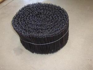
| Packaging Details: | Paper Roll,Iron Spool,Wooden Spool,Plastic Spool,Gift Box, Poll-out Box,Spools,Wooden Drums,Pallets and according to request |
|---|---|
| Delivery Detail: | 7days |
Specifications
our products:
1. Best price in the same quality.
2. Highest quality in same price
3. A good after-sales service
APPLICATIONS:
ACSR has the established reputation for economy and dependability in power
transmission lines. Also used for primary and secondary distribution lines. Wide
range of steel content from 7% to 40% can be achieved by different stranding, to
meet desired strength. Electrical losses by corona effect are greatly reduced, due to
the larger diameter size of this design. Economical transmission and distribution of
electrical energy can be achieved by ACSR, at very high voltages and distances.
SPECIFICATIONS:
ACSR Aluminum Conductors Steel Reinforced for High Voltage (HV) and Medium
Voltage (MV) Transmission Overhead Lines are usually manufactured according to
ASTM B232, BS 3242, DIN 48204, TS IEC 1089
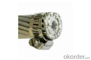
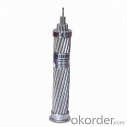
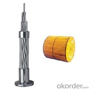
CONSTRUCTION:
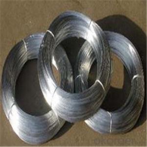
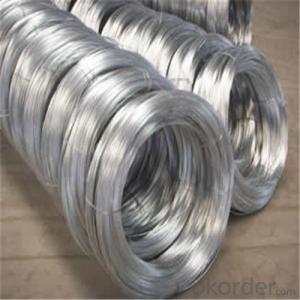
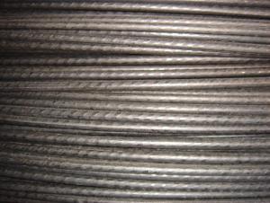
ACSR is a composite concentric-lay-stranded conductor. Galvanized steel strand or
strands form the central core of the conductor, around which is stranded one or
more layers of EC Grade Aluminium wires. The steel core may consist of a single
strand or a concentric stranded cable of 7, 19, 37, or more wires. Numerous
combinations of aluminum and steel strands and layers are possible.
FEATURES AND BENEFITS:
ACSR conductors are recognized for their record of economy, dependability and
favorable strength / weight ratio. ACSR conductors combine the light weight and
good conductivity of aluminum with the high tensile strength and ruggedness of
steel. In line design, this can provide higher tensions, less sag, and longer span
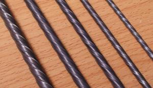
lengths than obtainable with most other types of overhead conductors. The steel
strands are added as mechanical reinforcements. The cross sections above
illustrate some common stranding. The steel core wires are protected from
corrosion by galvanizing.
- Q: for standard electric wiring, do I cut the white wire or the black wire to not get shocked?
- in case you have customary fencing up already and are only including a strand on the proper that your horse does not challenge besides, electric powered cord is okay. that's greater low-value; however the heavier gauge actual is far less risky than the skinny gauge IF the pony ever gets caught in it. Ribbon tape is safer. you may decide the only million/2 inch stuff for this objective. The signs and indicators are only small plastic or vinyl ones asserting that the fence is inspired. some screw into wood posts or rails, some clip suitable directly to the cord. Any farm shop has them the place the insualtors are bought. If young little ones are dumb sufficient to pour milk over the fence, they are too dumb to study signs and indicators. however the signs and indicators cut back your criminal accountability if one claims that they at the instant are concepts lifeless because of the fact they have been given bowled over. (Amber, that's a tongue-in-cheek remark.)
- Q: i recently replaced my spark plug wires on my 97' lincoln continental. i was wondering if i should get plug wire shielding for them also......thanx
- If it needed wire shielding it would have come with it from the factory. If you get OEM style plug wires then it will come with shielding as well, hence OEM, if not then it didn't come with them and doesn't need them.
- Q: ok so the passenger side back floorboard was getting wet and i believe the water to have corroded the wiring to my radio i've taken care of the water problem and know how to reconfigure the wiring but do i need to be worried about the security system while tinkering with the wiring see as how sensitive the security in these cars are i figured id check and see what you guys have to say about this pls also give resources as to how you know
- If you are going to replace wire by wire , you can do that first unplug the battery and be very care full with orange and pink wires, try to solder the new wires the factory amplifier is in the trunk left side good luck new wiring is $700 from the dealer and the only place to buy it new good luck
- Q: I'm faced with a dilemma...I'm wiring my basement right now and all is fine, except for my living room. I want to have a 3-way switch setup, but with four light fixtures. I've already ran 3+ground wires in this order...Breaker box - Switch A - Fixture 1 - Fix. 2 - Fix. 3 - Fix. 4 - Switch B. I have done regular 3-way switches in the past, without much trouble, but I have no idea how to wire this, so well-explained instructions would be perfect.Thanks so much!
- i hope i can give you good instructions. you have 2 switches you want to operate the lights. first. pull a feed or wire that will be hot probarly from your panel box to the easiest switch to get to. this wire should have 1 black 1 white and one bare copper or green. second pull a three wire from one switch to the other. this wire should have one black one white one bare copper or green and one red wire in it. now there are 2 different ways to go from here. one way. pull a wire from the switch opposite of the switch with the feed in it. this wire would be called a 2 wire it should have 1 black 1 white 1 bare copper or green, to the first light you want to operate. then you can pull a 2 wire from that light to any other light you want to operate from the switches. you do not need to pull any more wires from the lights to the switches. in the first switch with the feed take the white wire from the feed and tie it to the white wire from the 3 wire going to the other switch. take your grounds and tie them together. leave a wire from your grounds so you can tie it to the switch. put you white wires back into the box. you should have 2 blacks 1 red and 1 ground wire sticking out. when you install your switch a three-way switch has 4 screws on it. the ground goes to the green screw. now you have one black screw and 2 gold screws. the black wire from your feed wire ties to the black screw. the red and black wire from your 3 wire ties to the gold screw. one wire to on screw the other wire to the other screw. does not matter which. the opposite switch hooks up the same. the 2 white tie together and go into box. the grounds tie together and then tie to the green screw. the black wire going to your lights ties to the black screw and the red and black wires from the 3 wire go to the gold screws. remember if you are using 14 wire you can only put 12 amps on it that would be about 1400 watts. 12 wire you can put 16 amps on it which is 1900 watts.
- Q: While updating the parents basement we needed to replace a very very old 3 way switch. However, the wiring to the Fluorescents seems extreme to me. Here is how i can describle the layout. Panel - junction box - double splice (one to light fixture and one to threeway switch below it)-. From that threeway switch 12-3 wiring to upstairs landing with other threeway switch resides. How should I make my connections to switches? If the other swtiches were not so old I would just copy them.
- John has described the three way circuit for you. Your description matches his description. Good paradigm for amateur fiddlers with wiring: If it works, don't try to fix it.
- Q: I was looking at the wiring of my current thermostat and I want to know why it's wired the way it is...The yellow wire was wrapped around the white terminal and the yellow terminal. And the white wire was wrapped the around the Orange terminal. The red and green wires were each wrapped around their respective terminals. And the blue wire wasn't connected to anything. Why would the electrician have wrapped the yellow wire around 2 terminals? Is that normal? Also, I tried installing a new thermostat but the heating is not working. The fan works but it just blows room temperature air. The new thermostat only had 4 terminals for R, Y, W, G. I connected the wires I had to their respective terminals. However, I think it may not be working because I have a probably have a heat pump. Any Ideas why else it might not be working? Thanks a lot!
- Yeah it sounds like you have a heat pump and it is wired VERY basically. Your new thermostat will not work because it has no O terminal. You will have to buy a heat pump t-stat then wire it the same way your old one was and it should work fine. In other words Red to R and Rh if it has one, Green to G, Yellow to Y *AND* W, and White to O. Basically what's being done the way your old t-stat was wired is the compressor is being brought on in heat or cool and the white wire on O is switching your reversing valve for cooling mode. The way you have the new one wired is just going to switch the reversing valve and turn the fan on and won't bring the compressor on when the heat is called to run. If your system has backup heat, that extra blue wire could be used to bring the backup heat on if it is re-wired to do so. If your going to have it re-wired I would change the wiring so blue was the reversing valve and white was the backup heat. This would require re-wiring both indoor and outdoor units if it is a split system or re-wiring the package unit if it is that type. Or if you really want it done right have new thermostat wiring run and have it wired properly for a heat pump. If you don't want to go through all of that just buy a heat pump stat and wire it like your old stat.
- Q: I have a 2000 Subaru Outback, and I can get the thing working, but it does not save any of my settings. i know its my accessory wire because the radio will not turn on from any other wire.. soo help please
- There are two wires that you must hook up. One is for continuous power so that the settings are saved, the other is for power to the radio. If you had purchased your equipment from Crutchfield, you would have gotten free installation instructions and a wiring harness that would hook directly to your Subaru wiring - saving you a great deal of time and trouble.
- Q: My light switch has three sets of three wires (like conduit).. there are three black wires, three white wires, and three bare wires.. and I don't know how to hook up another light switch because it's near impossible to get three wires around a screw terminal. My boyfriend (works in maintenance) hooked a light switch up (one that you put the wires in a hole and then screw) except for the bare wire where two wires are under the screw terminal and the third is wrapped around the other two bare wires. The lights will stay on but when you turn the switch off, it kicks the breaker.. can anyone tell me why it's doing that? Thank you.
- What it sounds like is happening there is that the switch box is the main feed for the room. You have a set from the panel, a set for the light fixture, and a set that are downstream, such as for an outlet. You need to determine which set is which. Then cut a piece of black wire and a bare copper about 8 long. This is how the connections are made: TURN THE POWER OFF. Then connect all of the whites together with a wire nut. Connect the new bare copper to the other grounds with another wire nut. Then connect the black from the panel, the downstream black, and the short black together with another wire nut. The black to the light fixture and the black pigtail (short wire) connect to the 2 brass terminals on the switch. The bare copper pigtail goes on the green screw on the switch. Reinstall the switch in the box, turn the power on, and check your work. If the light stays on at all times, but the outlets only work when the switch is on, those 2 wires are reversed. Turn the power off, switch the wires, and you should be good to go. Hope this helps.
- Q: What do you use to seal up the hole in the OUTSIDE wall where the cable TV and telephone wires and electrical wires all go thru? I want to replace my telephone wire coming in to the house, because I have DSL and it is really slow. I figured it couldn't hurt to replace the 45 year old wire coming in! :D I'm gonna use the best wire I can find (ANY SUGGESTIONS on what kinda wire to get? :D) to go from the telephone box outside to the DSL jack, but I need to no what to use to seal up the outside hole, when I rip out whatever is plugging it up now! :DThanks! ~Cindy! :D
- Cat 5e cable for the DSL. Clear 100 percent silicon calk for the hole. Keep the factory twists in the cat 5 pairs for as close as you can get them to your terminations for speed. Clean the terminal connectors where you connect the wires. Keep the cat 5 away from electric wires as much as possible. Good luck.
- Q: A wire has resistance 56.8 ohms. If another wire consists of the same material but has twice the length and half the diameter of the first, what is the resistance of the 2nd wire?
- Resistance = rho * L/A where rho = resistivity of the material, so it's the same for both wires. You've doubled the length, and you've divided the area by a factor of 2^2 = 4. Calculate rho * (2L)/(0.25A) and compare that to rho * L/A.
Send your message to us
ACSR LARK (ASTM - B 232) with competetive price
- Ref Price:
-
- Loading Port:
- Tianjin
- Payment Terms:
- TT OR LC
- Min Order Qty:
- 1000 m.t.
- Supply Capability:
- 100000 m.t./month
OKorder Service Pledge
OKorder Financial Service
Similar products
Hot products

Hot Searches

