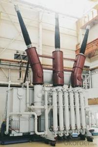

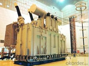
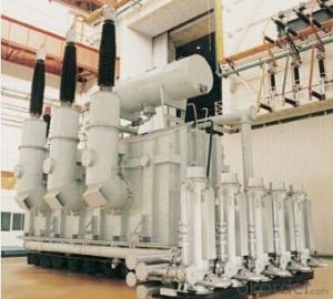
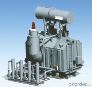
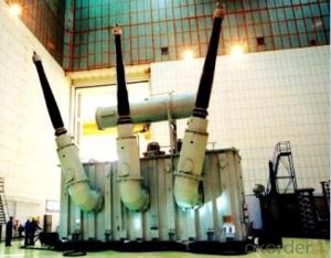
840MVA/550kV three phase water cooling main transformer for the hydro power station
- Ref Price:
-

- Loading Port:
- Tianjin
- Payment Terms:
- TT OR LC
- Min Order Qty:
- 1 pc
- Supply Capability:
- 1 pc/month
OKorder Service Pledge
OKorder Financial Service
You Might Also Like


Quick Details
| Place of Origin: | HeBei | Brand Name: | CNBM | Model Number: |
|
| Usage: | Power | Phase: | three | Coil Structure: | Toroidal |
| Coil Number: | Capacity: | Rated Voltage: | 840MVA/550kV | ||
| Connection Symbol: | YNd11 Dyn11 YNyn0d11 | Tank: | Cover type or Bell type | OLTC: | MR or ABB or SMS |
Packaging & Delivery
| Packaging Detail: | Mainbody --naked Disassembled parts -- crate |
| Delivery Detail: | 3 months |
Specifications
1. CESI certificate
2. High short-circuit withstand
3. Low loss, PD and noise
4. CTQC certificate
5. No leakage
Description
The application of the 840MVA/550kV three phase water cooling main transformer for the hydro power station.can significantly improve the economy of the OLTC substation, and matches well with the transmission capacity of OLTC lines, which has wide prospect of application. Because of its large capacity and large volume, the whole transportation weight with nitrogen is about 470-490 tons, and due to the restricted transport conditions, the transportation becomes the critical issue for the 840MVA/550kV three phase water cooling main transformer for the hydro power station. In order to make the products applicable to any OLTC substation in our country, the state grid of corporation of China set the "A study of easy-transport large capacity OLTC Transformer” as a key scientific research projects, and entrusted BTW to carry out the research.
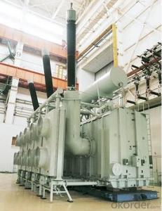
During the process of research and development, BTW adopted the advanced design technology and modular design, the transformer can be transported disassembly and with advantages of compact core and winding body, less transportation weight and low transportation cost, effectively solves the need of OLTC construction in the transportation restricted areas. By using the most advanced 3D magnetic field calculation software, BTW performed detailed analysis and calculation for the magnetic flux leakage and eddy current loss of the transformer coil, iron core and oil tank steel structures. Besides, by using of the advanced electric field calculation software, BTW performed detailed analysis and calculation of main longitudinal insulation, and mastered the arrangement of the main longitudinal insulation of large capacity OLTCtransformer and the control of distribution of winding magnetic flux leakage. All of which make the products with low loss, low noise, small volume, strong anti short circuit ability, no local overheating and other significant advantages, and guarantee the long-term safe and stable operation.
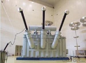
The world's first on-site assembled large capacity OLTC Transformer’s right at the first time once again filled the gap in the field of OLTC transformer research after Chinese transformer industry overcame the difficulty of integral transport of the 840MVA/550kV three phase water cooling main transformer for the hydro power station, which marks BTW has fully occupied the world transformer industry technical peak. The successful development of the product filled the gaps in the domestic technology and met the urgent need of OLTCconstruction application in our country, greatly improved the technical level and manufacturing ability of BTW in terms of OLTC Transformer products.
- Q: I am powering a lighting system with a mixture of SCR dimmers and HID lamps. I am pulling approx 285 amps/leg at 120/208V through a 150 kVA transformer. The 120/208V service coming from that transformer is indicated to be 400A/leg, but it seems to get pretty hot at 285A.
- Three phase transformers are given a power rating which is the sum of all three powers on each phase. So 285 amps on each phase at 120 line to neutral (assuming this is how youve them connected) is about 35kva, so about 100kva all up. What is actually on the name plate of the transformer? How hot is 'pretty hot'? Is it running as it was desinged (oil, dry, forced air cooling etc). Also how are your lamps/dimmers wired? The other answer is correct, the dimmers will produce alot of harmonics. The meter your are using to read the current is most likely designed to read a 60hz sine wave, any other stuff there will cause a wrong reading (they usually measure the average value, then apply a correction factor to obtain the rms value. But this factor depends on the wave shape, if its not a sine wave it will be wrong). See if you can obtain a meter that will measure the true RMS current. Transformers of that size are usually heavily over engineered, it should be fine as long as the tempertature doesnt continue to increase, ie to the point where the case is too hot to touch. As the other answer said it is probably rated for continuous operation at about 75 degrees. Id not worry too much as long as the temperature doesnt continue increasing.
- Q: I know that a step up transformer (stabilizer) increases/decreases the voltage that is received from the main electrical lines thus allowing gadgets to work properly. Keeping this in mind will the following idea work:1.You start a motor with the help of a battery,2.The motor then turns a dynamo using a strap (connected like a chain on a bicycle) 3.The dynamo produces electricity, this electricity is sent through a step up transformer, this then increases the output of power received from the dynamo.4.This increased power is then sent to a set of plugs, where devices can be plugged in to use the increased power. One permanent plug/use will be to recharge the battery or to run the motor by using a changeover switch (battery to motor ---- output from dynamo to motor)
- As okorder
- Q: I know that vector groups basically determine the phase shift, and paralleling two transformers with different phase shifts is a genuine disaster.Some phase shifts can occur due to difference in the dot place, but for Wye-Delta connection the phase shift is 30 degree even with same dot on the primary and secondary. Why ?
- Phase Shift Transformer
- Q: Why the new operation of the transformer to be charged
- New installation or overhaul after the transformer, have to carry out the explosion test, test the performance of the transformer. The general impact of 3 to 5 times, the first impact of transmission for about 15 minutes, after every 5 minutes each time the impact of a time, about 10 minutes each time. ????? 1, test transformer insulation, mechanical strength can withstand the impact of working voltage and excitation inrush. ????? 2, test whether the transformer differential protection can avoid the impact of inrush current.
- Q: I bought a 110 v AC transformer to run an item that requires 24.5 v DC. the transformer I bought is 110 v Ac to 30 v DC. can I put a rheostat inline (at the dc end before the unit to be powered) to adjust the voltage output ? and if so, Where do I find one?
- Transformers do not rectify and filter the output. It's AC in and AC out. A transformer either steps up the voltage or steps it down, depending upon direction. A transformer is only the first step in converting 110vac to a DC voltage. After the transformer has stepped down the 110v to 30v (AC!), it needs to be rectified into pulsating DC. Using 2 diodes (half wave rectifier), the DC will be 21v (still pulsating an unreliable for your use). If you use 4 diodes (full wave bridge), the resultant pulsating DC will be 42v. Now you need to filter it using capacitors so that it's a steady DC. You COULD use a potentiometer (rheostat) in a voltage divider network to dial down the voltage that you want to use, but fluctuations in the 110v will still be transmitted to the finished DC. So you also want to use a voltage regulator chip. That way, you get a steady, filtered, reliable DC voltage.
- Q: I live in US and I will move to my home country where 240V is supplied in the power sockets.I'm planning to ship my computer, LCD TV, speakers, game console, etc. and buy a power transformer. However, I'm afraid the power loss in the transformer will raise my electric bill so in the long run, it's not worth it to ship my electrical appliances.So how much is the typical power loss in a 120/240V step up transformer? The range of efficiency would help.
- A lot of smaller appliances will operate on a range of voltages, 120 or 240 volts. check the documentation for something like 100-250 VAC 50/60Hz. If you see that, all you need is a plug converter, or, if the move is permanent, just cut off the plug and put on the correct one. So check each one first, and for those that need a transformer, add up the wattages to get a total, so you can get the correct size transformer. PS, for high wattage items, like a hair dryer, just toss and buy a new one, it's not worth the high cost of such a large transformer. It's actually cheaper to get a new unit. For the TV, most all US TVs won't operate in most other countries because of different broadcast standards (NTSC vs PAL vs SECAM, 50Hz vs 60Hz, and different frequency bands). I'd check that carefully beforehand, but offhand, I'd say forget the TV. When you get done all of this, you may not need a transformer, or only a small one. Losses in the transformer are less for a small unit, and are less when the load is low. I'd say 5% or less. If you wind up with a 200 watt transformer (which is big, but not the 3000 watt size you would need for a hair dryer), losses will be small, perhaps 10 watts, perhaps less. .
- Q: I want to run a electric motor at 6v from a wall outlet. I need to know what wall plug transformer rating I should use to run it. Here is what I have.
- It okorder
- Q: Hello forum,I have a question pertaining to transformers. I understand the current oscillating in a coil of wires around a toroid-type metal induces a moving magnetic field in the metal, which induces current in another set of coils on the other side, right? If I'm slightly correct, yay1) Are transformers specifically AC? Can there be DC transformers or would I have to rectify it after it's been stepped-down?2) Is the output voltage independent of the current? Let's say I have 50W, 120V stepped-up to 240V. If I change the power supply to 100W, will the voltage still be stepped up the same, while current would be twice as high? (Ideally)Thanks!
- Why do no longer you employ the inverter as a replace of transformer to grant the ordinary. on a similar time as layout a transformer you will desire to evaluate (i) the losses in the winding. (ii) bypass area area of the conductor (iii) yoke bypass area I advise you to apply a inverter to feed the ordinary. and view the losses. The losses basically that lots of voltage dropped. observe: buddy transformer designs are no longer a large deal. purchase a transformer in shop and notice the progression element. focus greater on capability electronics, that's warm style now.
- Q: 10 (6) /0.4kv three-phase transformer what does it mean
- Therefore, the decision to 60 and 35kV winding connection to be careful when the connection must meet the transmission system voltage phasor requirements. The connection between 60 and 35kV windings is determined according to the relative relationship of the voltage phasors. Otherwise, even if the capacity of the voltage ratio is also right, the transformer can not be used, connected wrong, the transformer can not be connected with the transmission system. 3). Domestic 10,6,3 and 0.4kV transmission and distribution system phase also has two phases. In the Shanghai area, there is a 10kV and 110kV transmission system voltage phase difference of 60 ° electrical angle, this time can be used 110/35 / 10kV voltage ratio and YN, yn0, y10 connection three-phase three-winding power transformer, but limited Three-phase three-core core. 4). But note that: single-phase transformer in the combination of three-phase group connection, can not use YNy0 connected three-phase group. Three-phase shell-type transformer can not use YNy0 connection.
- Q: Transformer insulation level L175 AC35 / 5 What does it mean
- 2, the insulation level of the transformer is according to the high pressure, medium voltage, low voltage winding sequence listed in the tolerance voltage value (the impact level in the former), during which separated by a slash. The neutral insulation level of the graded insulation is followed by a horizontal line at its wire end insulation level. Such as: LI850AC360-LI400AC200 / LI480AC200-LI250AC95 / LI75AC35. Meaning: 220KV three-side insulation of the main transformer, high-voltage side of the lead-side lightning impulse withstand voltage is 850kV, power frequency withstand voltage is 360kV, high-voltage side of the neutral point of the terminal lightning impulse withstand voltage is 400kV, power frequency resistance The voltage is 200kV;
Send your message to us
840MVA/550kV three phase water cooling main transformer for the hydro power station
- Ref Price:
-
- Loading Port:
- Tianjin
- Payment Terms:
- TT OR LC
- Min Order Qty:
- 1 pc
- Supply Capability:
- 1 pc/month
OKorder Service Pledge
OKorder Financial Service
Similar products
Hot products


Hot Searches
Related keywords

