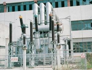
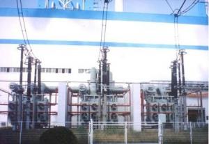
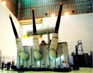
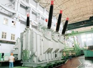
370MVA/535kV main transformer power plant
- Ref Price:
-

- Loading Port:
- Tianjin
- Payment Terms:
- TT OR LC
- Min Order Qty:
- 1 pc
- Supply Capability:
- 1 pc/month
OKorder Service Pledge
OKorder Financial Service
You Might Also Like


Quick Details
| Place of Origin: | HeBei | Brand Name: | CNBM | Model Number: |
|
| Usage: | Power | Phase: | one | Coil Structure: | Toroidal |
| Coil Number: | 2 Winding | Capacity: | Rated Voltage: | 370MVA/535kV | |
| Connection Symbol: | YNd11 Dyn11 YNyn0d11 | Tank: | Cover type or Bell type | OLTC: | MR or ABB or SMS |
Packaging & Delivery
| Packaging Detail: | Mainbody --naked Disassembled parts -- crate |
| Delivery Detail: | 3 months |
Specifications
1. CESI certificate
2. High short-circuit withstand
3. Low loss, PD and noise
4. CTQC certificate
5. No leakage
Description
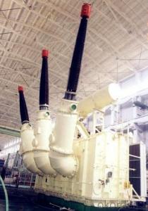
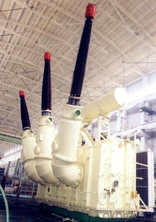
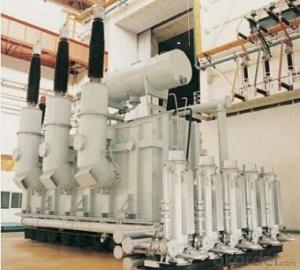
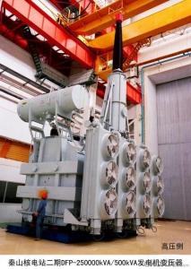
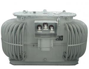
The application of the 370MVA/535kV main transformer power plant.can significantly improve the economy of the OLTC substation, and matches well with the transmission capacity of OLTC lines, which has wide prospect of application. Because of its large capacity and large volume, the whole transportation weight with nitrogen is about 470-490 tons, and due to the restricted transport conditions, the transportation becomes the critical issue for the 370MVA/535kV main transformer power plant. In order to make the products applicable to any OLTC substation in our country, the state grid of corporation of China set the "A study of easy-transport large capacity OLTC Transformer” as a key scientific research projects, and entrusted BTW to carry out the research.
During the process of research and development, BTW adopted the advanced design technology and modular design, the transformer can be transported disassembly and with advantages of compact core and winding body, less transportation weight and low transportation cost, effectively solves the need of OLTC construction in the transportation restricted areas. By using the most advanced 3D magnetic field calculation software, BTW performed detailed analysis and calculation for the magnetic flux leakage and eddy current loss of the transformer coil, iron core and oil tank steel structures. Besides, by using of the advanced electric field calculation software, BTW performed detailed analysis and calculation of main longitudinal insulation, and mastered the arrangement of the main longitudinal insulation of large capacity OLTCtransformer and the control of distribution of winding magnetic flux leakage. All of which make the products with low loss, low noise, small volume, strong anti short circuit ability, no local overheating and other significant advantages, and guarantee the long-term safe and stable operation.
The world's first on-site assembled large capacity OLTC Transformer’s right at the first time once again filled the gap in the field of OLTC transformer research after Chinese transformer industry overcame the difficulty of integral transport of the 370MVA/535kV main transformer power plant, which marks BTW has fully occupied the world transformer industry technical peak. The successful development of the product filled the gaps in the domestic technology and met the urgent need of OLTCconstruction application in our country, greatly improved the technical level and manufacturing ability of BTW in terms of OLTC Transformer products.
- Q: How do transformers work detailed descriptions please. Also how are the voltages stepped up or down?
- Transformers can e used only for A.C the fluctuating current in the primary coil produces a magmetic field.this magnetic field by mutual induction makes a current in secondary coil The no:of turns in primary and secon determines thr rating of transformers more the no:of turns more magnetic field will be produced in primary and less the no:of turns in the secon lesser will be the current induced and vice versa For more details visit
- Q: I need this Radio Shack transformer to provide power to a HO scale model train board lighting system. This transformer will be connected to a brightness control system and then the brightness control system will be connected to building lights and street lights. I have been told this issue is a safety and Electrical Code concern?
- a acceptable web site. Face the construction south with residing house windows in basic terms in the south elevation. the north elevation could the two have a small variety of small residing house windows or be breamed with earth. For an present residing house, Geothermal is huge in case you have the money. the traditional forced warm air gadget that maximum US properties has is likely considered one of the main effective for the preliminary value and maintenance in comparison to the warmth is generates. A German business enterprise, called viessman (sp) creates very useful structures for this configuataion.
- Q: I have 13 lights with 12 volts 35 Watts on each light for each tree, the outlet is 120 volts current now. Should I buy 300Watt or 600Watt low volts transformer to supply all lights? Need your advise!
- you need to drop lights down to 25 watts ,and use the 300 , the 600 is just 2 300s not a solid 600. check out malibu lights web site.
- Q: I remember a Transformers cartoon and there was like a gas in it and if the Autobots were in a place that the gas was in there, they would turn red and turn evil and fight each other. And also Optimus Prime was dead fist and then some Autobots bring him back to life And I think Rodimus has the matrix. What was that movie called?
- Yup, that was the episode in season three where Optimus Prime is brought back to life (after his death in the movie). The episode is called Return of Optimus Prime and is a two parter. The red stuff is rage and can pass if you get touched a la 28 days later. This is the episode that had Optimus return to life and get back the matrix from Rodimus (turning again back to Hot Rod). He unleashed the matrix to defeat the rage, but it empties the matrix of all it contained.
- Q: Do stores that sells computers, printers, etc. also sell transformers
- Transformers as in the action figures? You can find them at Toys R Us, Wal*Mart, or Target.
- Q: If you have two 12 volt transformers and if we connect their hot wires together does the voltage become 24 or 12 volts?
- There is actually a phasing to the transformer windings. If you connect them in series with the phases adding (both hit + 12 at the same instant) you get 24 volts out. If you connect with the phasing wrong (one hits +12 while the other hits -12) and put them in series the output will be zero volts (and they might overheat). If you connect them in parallel with the right phasing you will get 12 volts and the amperage will add to give you the sum of their amperage. If you connect in parallel with the phasing wrong you will get zero output voltage (and the danger of overheating). If the transformers do not make their phasing clear put a voltmeter on the output and briefly turn on the primary while seeing if you get zero or the voltage you want. If the phasing is wring swap the wires of one transformer around and check with the meter again.
- Q: I have 2 flyback transformers one is from an old TV and the other one is from an monitor (new).I need to know the negative pin for the HV (high voltage)and the pins from the primary coil (input) and primary coil polarity. Can you tell me a method to find out these things? Thank you
- reference 1: The flyback circuit diagram calls for two sets of coils: a primary coil and a feedback coil. The turn ratio is really not that critical so usually ANY two coils in the flyback primary will work. Locate two sets of coils on the horse-shoe-like configured pins by testing the flyback pins for continuity. Often times there are more than two pins connected to a single coil in the transformer. You will need to try the different positions to see which configuration works better for your application. After you have located two independent sets of coils on your flyback, hook them up to the circuit with any polarity. If you turn on the power any you don't hear a whine or hum, try reversing the polarity (switch the leads) of ONE of the coils. If nothing now, reverse the polarity of the other coil. If nothing now, reverse the polarity on the first one you switched again. So the take home message is trial and error. Flybacks can be very picky as to coil polarity because some of them have a rectifier built in them. So try each configuration (8 of them with two sets of coils) until it whines (Occasionally I'll find one that doesn't wine but VERY rarely). Any two sets of coils in a potted flyback should work, so don't try new coils until you're sure you've exhausted all possible combinations. The high voltage will come out of the fat wire from the top of the flyback-usually connected to the CRT with a suction cup. You will not be able to locate the high voltage return pin with a multimeter. The only way to do it is to bring the high voltage line down to the pins and whichever one it arcs like mad to is the one yer looking for. Try to stay away from arcing to any of the pins used for coils. High voltage is not so good for your transistor or power supply. second reference has a lot of useful info plus photos. . .
- Q: Transformer and the middle of what is the difference
- In the week is the IF transformer or inductance coil, is a fixed resonant circuit with a transformer, the resonant circuit can be fine-tuning within a certain range, so that access to the circuit can achieve a stable resonant frequency.
- Q: how transformer came to know that it has to draw lagging current during summers
- it does not have a clue about seasons. transformers are inherently inductive devices and thisn means current lags any day of the year
- Q: I am installing a humidifier. It comes with a 120vac to 24vac transformer to be installed. The transformer has a label on it that says install in electrical box only. One side of the transformer is designed to screw into an electrical box knockout and has leads coming through the middle of this for connection to the 120VAC input.Is the transformer supposed to be screwed into the electrical box on the outside or the inside. At first, I assumed inside but this would result in my connection leads being on the outside. ThanksBill
- bill its supposed to be mounted to the board area of the furnace, the black and white 110 leads go on the board of most furnaces you must add the spade connectors, then run your two wire to the controls and wire nut them to the colored wires on the 24v side. if you cant mount this to the board then zip tie it to the wiring harness.
Send your message to us
370MVA/535kV main transformer power plant
- Ref Price:
-
- Loading Port:
- Tianjin
- Payment Terms:
- TT OR LC
- Min Order Qty:
- 1 pc
- Supply Capability:
- 1 pc/month
OKorder Service Pledge
OKorder Financial Service
Similar products
Hot products


Hot Searches
Related keywords

