

Gate Valve with Ductile Iron for Water System
- Ref Price:
-

- Loading Port:
- China main port
- Payment Terms:
- TT or LC
- Min Order Qty:
- 1000 set
- Supply Capability:
- 50000 set/month
OKorder Service Pledge
OKorder Financial Service
You Might Also Like
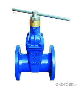
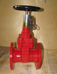
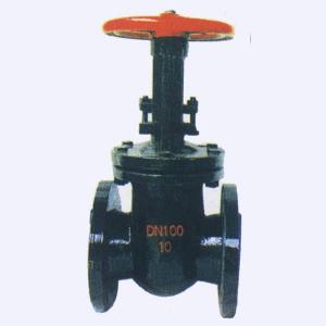
1. Structure of Gate Valve Description:
1. Selected materials, in line with domestic and international standards, high overall quality of the material.
2. In line with the requirements of domestic and foreign advanced standards, reliable sealing, excellent performance, attractive appearance.
3. Sealing pair advanced and reasonable, gate and seat sealing surface with different hardness Stellite (Stellite) cobalt-based alloy cladding made, reliable sealing, high hardness, wear resistance, high temperature, corrosion good anti-abrasion performance, long life.
4. Stem quenched and nitride surface treatment, has good corrosion resistance, scratch resistance and abrasion resistance.
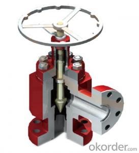
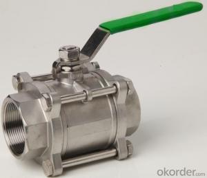
2. Main Features of the Gate Valve:
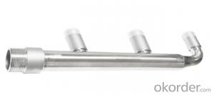
stainless steel flanged gate valve Z45T-10 valve uses wedge-type elastic single gate structure, apply to the temperature less than or equal 135 degrees of water, steam, oil in pipeline and other media to open and close. Main features: body is made from precision casting, sleek style seat closed plate tightly ,reaching no leakage, no sediment, circulation, smooth, open and close flexibly.
1)Full port design
2)OS&Y Outside screw and yoke .
3)BB. Bolted Bonnet .
4)Flexible wedge, Fully guided
5)Choice of solid or split wedge .
6)Renewable seat rings
7)Forged T-head stem
8)Rising stem and non-rising handwheel
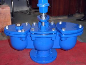
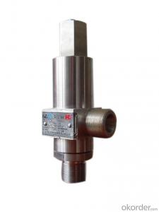
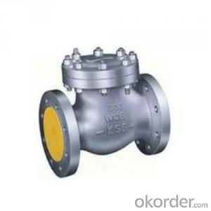
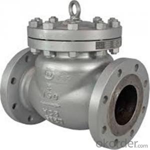
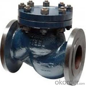
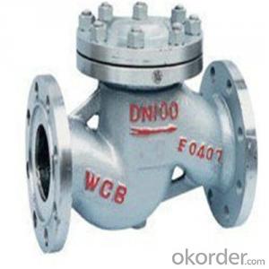
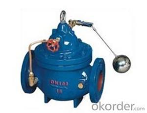
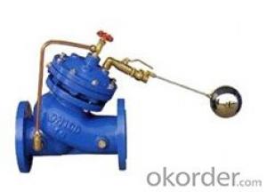
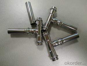
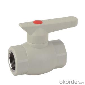
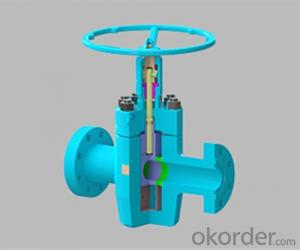
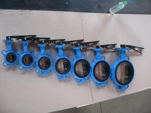
3. Images of the Gate Valve:


4. Specification of the Gate Valve:
1.Material:A105,A105N,F304,F304L,F316,F316L,LF2,F5,F11,F22,F347,F321,F51,Monel......
2.Size:≤3"
3.Pressure: Class150~2500
4.Design and Manufacture:API602,BS5352,ANSI B16.34
5.Connection Ends:
1)Socket Welded Dimension:ANSI B16.11,JB/T1751
2)Screw Ends Dimension:ANSI B1.20,JB/T7306
3)Butt Welded:ANSI B16.25
4)Flanged Ends:ANSI B16.5,JB79
Design according to DIN3352-F5
Flange drilled according to DIN2501
Body: Ductile iron
Wedge: Ductile iron with NBR/EPDM
Stem: Stainless steel 2Cr13
Stem Nut: Brass
O-ring: NBR/EPDM
Bolt & Nut: Carbon steel or Stainless steel
Bonnet: Ductile iron
5.FAQ
1. Can I get free samples?
A: Yes,we can provide you the free sample, but you need to bear their own delivery costs.
2. Can I request to change the form of packaging and transportation?
A:Yes, We can change the form of the packaging and transportation according to your request, but you have to bear their own costs incurred during this period and the spreads.
3. Can I request to advance the shipment?
A: It should be depends on whether there is sufficient inventory in our warehouse.
4. Can I have my own Logo on the product?
A: Yes, you can send us your drawing and we can make your logo, but you have to bear
their own the cost.
5. Can you produce the products according to my own drawings?
A:Yes,we can produce the products according to your drawings that will be most satisfy you.
- Q:How can I tell if my 2004 Ford Taurus a 12 or 24 valve?
- I may be wrong but I think the 24 valve engines had a little badge on the body of the car that said 24 VALVE. Another thing that might help is look at the engine information on the white tag under the hood.
- Q:I've been told that I need to replace a clogged expanssion valve on my '96 toyota camry.A friend said he would properly recharge the system if i replaced the parts needed .I can't ask him where it is because he's out of town for a little while. I also need to replace the drier ,but it's obvious where it is.Please help me.
- the expansion valve is usually located inside the line next to the accumulator/dryer. If you drain the system, and remove the accumulator, look inside the line that leads into it, and it should be stuffed in the line. If you see one inside the line, it is actually called an orifice tube, but has the same function as an expansion valve. Actually, expansion valves are usually used in large vans with a rear a/c evaporator unit. If it is an external valve it should be next to the accumulator as well. The purpose of this valve/tube is to create high pressure gas out of low pressure liquid freon. These usually become clogged with debris after the compressor's pistons break apart and contaminate the system. If you find little metal shavings in the tube, or valve, your compressor was either replaced at one time, or is bad now.
- Q:I am working on my riding mower Briggs and Stratton 15.5 OHV. After replacing my headgasket my intake valve did not move when I turned shaft by hand. I took it back apart and believe I have my pushrods positioned correctly but cannot seem to get the rockkers back over the valves and rods. Maybe its because I am a girl and just need to man up but I thought it should be easier. Anyone got any tips?
- Okay, here we go. I have been doing this for 150 years, so I think I know why you are having the problem. The piston must be at Top-Dead-Center (TDC) on the FIRING stroke. Both valves will be what is known as On The Rock. That is or means the push-rods will be resting on the camshaft inside the engine where there is no lift (bottomed). The best way to find this out is to look at the flywheel and see where the magnet is in relation to the ignition coil. The engine actually fires twice (it's just the way it is), but if yo see the magnet on the ignition coil then chances are you are either at TDC on the compression stroke or BDC on the induction stroke. Confused yet? Let's make it easy to tell the difference. When the piston is at TDC the piston will be at the to p of the bore and the magnet will be on the ignition coil. The valve push-rods will be at the same height. This is when you fit the rockers. As you can see there will be two nuts or a single nylock nut that has a nylon insert. If you have the nylock nut then then just tighten the inlet to 0.007 and the exhaust to 0.010. The same applies with the two nut system, except that when you have set the gaps you have to spin the locking nut down and hold the set nut (the first one) and then tighten the other nut down tight to the set nut. But I guess you knew all this, eh. Good to go, eh. I hope I might have been some help. mmalky: 50 years fixing small and large lawnmowers.
- Q:Ford Capri 2.8 injection. I need to adjust the valves, so need to know how to tell if the valves are tipping and at what exact time I need to adjust them.
- valve tapping what is valve tipping search yahoo answers for valve tapping i saw a resolved question about how to fix this problem
- Q:Valves regarding WC's
- The proper names of the two valves in a typical home toilet are the flapper valve and the ballcock valve. The flapper valve sends water from the tank to the bowl during the flushing of the toilet. The ballcock refills the tank and also sends a small amount of water to the bowl during the flush.
- Q:In one of the two bathrooms - that we rarely used - I recently found that shower has now only hot water running. The valve is Moen brand with a single knob. On turning this, I get no cold water, but just hot water. I removed the knob, and decided to maybe replace the cartidge, but could not make any headway, after removing the acrylic knob. First, do I need to remove the cartridge?If yes, how? Is it possible to remove it without removing the back-plate glued to the Tile walls? Will appreciate detailed instructions to remove or fix the valve?thanks
- the valve should have a c shaped clip holding it in. do that with the water shut off. if you have cold water to the tub spout, maybe the valve body is clogged with sediment, or a CW valve has collapsed.you have to remove the back plate to access the valve body.
- Q:This valve has flow indication embossed on their body.
- the gate valve is a very important one in flow measurement and also used to help the measure of flow. for example if you know the pneumatic comparator operation, you can easily under stand the gate valve. the gate valve is mainly used for to adjust the float in the tube to zero position or the clearance value.
- Q:i dont get how valves produce the sound? and why did we change to solid state? was that because they we're used in stereos?
- Most valve amps I have used reproduce the sound of a tube amp. Tubes have a warm sound and can be overdriven to get that good rock crunch distortion sound. We went to solid state because they were durable and didn't require the maintenance of a tube amp. Printed circuits and transistors cut the cost of manufacturing. The old tube amps still have the purpose and they never quite matched the exact sound of tubes with the solid state amps. That is why they are making a lot of tube amps now.
- Q:IT USUALLY TAKES 2 SECONDS TO START THE MOTOR. NOW, IT TAKES OVER 40 SECONDS AT 7 AM. IT ALMOST KILL THE BATTERY. IF YOU PARK FOR 1 HOUR, 2ND START TAKES 10 SECONDS. IS THIS HAPPENING BECAUSE THE VALVES NEEDS ADJUSTING? HOW AND WHAT IS THE EASY WAY OF VALVES TUNE-UP?
- MY MECHANIC TOLD ME: AT 9000 MILES, SCOOTER IS DUE FOR VALVE ADJUSTMENT. EVERYTHING ELSE SHOULD BE OK. 1] WAIT UNTIL MOTOR COOLS OFF 2] REMOVE PLASTIC VALVE COVER 3] LOOSEN RIGHT FENDER TO GET EASY ACCESS TO VALVES 4] USE 8 MM SOCKET TO TAKE OFF THE FOUR VALVE COVER SCREWS 5] USE 10 MM SOCKET TO TAKE OFF THE LAST TWO NUTS 6] REMOVE ALUMINUM VALVE COVER 7] PISTON MUST BE FIRST COME ALL THE WAY UP BEFORE ADJUSTING VALVES 8] CHAIN AND DISK HAS 3 HOLES, SET HOLE ONE UP, HOLE TWO DOWN, AND HOLE THREE TO THE LEFT [ IN THE MIDDLE BETWEEN THE TWO VALVES. 9] MUST HAVE A GAGE FEELER SIZE 3/1000, AND 4/1000 $7 SET AT ADVANCE AUTO 10] USE 9 MM SOCKET TO LOOSEN THE TOP INTAKE VALVE NUT USE GAGE SIZE 3/1000 ON TOP OF VALVE. ADJUST VALVE SCREW, NOT TOO TIGHT, AND NOT TOO LOOSE HOLD THE TOP SCREW WITH A PLIER WHILE TIGHTENING THE TOP NUT WITH 9 MM OPEN WRENCH. MAKE SURE THE NUT IS GOOD AND TIGHT. MINE WAS MOVED TO SIZE 7/1000 MM, THEREFORE, IT WAS HARD TO START. 11] USE 9 MM SOCKET TO LOOSEN THE BOTTOM EXHAUST VALVE NUT USE GAGE SIZE 4/1000 ON TOP OF VALVE. ADJUST VALVE SCREW, NOT TOO TIGHT, AND NOT TOO LOOSE HOLD THE TOP SCREW WITH A PLIER WHILE TIGHTENING THE TOP NUT WITH 9 MM OPEN WRENCH. MAKE SURE THE NUT IS GOOD AND TIGHT. MINE WAS MOVED TO SIZE 2/1000, IT WAS HARD TO START. 12] HOOK THE GROUND WIRE, AN CHECK IF IT IS EASY TO START 13] ONCE IT HAS GOOD START, PUT THINGS BACK IN REVERSE AS THEY WERE. 14] FIRST PUT COVER AND ALL SCREWS HAND TIGHT ONLY, THEN TIGHT THEM GOOD. I STARED TIGHTENING THEM ONE AT A TIME, THEN THE LAST ONE WOULD NOT FIT I HAD TO LOOSEN ALL OF THEM AND GET THEM ALL STARTED AND HAND TIGHT FIRST. 15] ADVANCE AUTO MAY LET YOU USE SOME LOANER TOOLS 16] PUT EVERYTHING BACK TOGETHER AND YOU READY TO GO FOR 5000 MILES. GOOD LUCK, WERE YOUR HELMET, AND DRIVE CAREFUL. TRY NOT TO DRIVE IN BAD WEATHER WEATHER LINK: www.spc.noaa /
- Q:Is what-valve spring. orvalve guide. orvalve cover. orretainer clip
- valve guide ase certified.
1. Manufacturer Overview |
|
|---|---|
| Location | |
| Year Established | |
| Annual Output Value | |
| Main Markets | |
| Company Certifications | |
2. Manufacturer Certificates |
|
|---|---|
| a) Certification Name | |
| Range | |
| Reference | |
| Validity Period | |
3. Manufacturer Capability |
|
|---|---|
| a)Trade Capacity | |
| Nearest Port | |
| Export Percentage | |
| No.of Employees in Trade Department | |
| Language Spoken: | |
| b)Factory Information | |
| Factory Size: | |
| No. of Production Lines | |
| Contract Manufacturing | |
| Product Price Range | |
Send your message to us
Gate Valve with Ductile Iron for Water System
- Ref Price:
-
- Loading Port:
- China main port
- Payment Terms:
- TT or LC
- Min Order Qty:
- 1000 set
- Supply Capability:
- 50000 set/month
OKorder Service Pledge
OKorder Financial Service
Similar products
New products
Hot products
Related keywords

