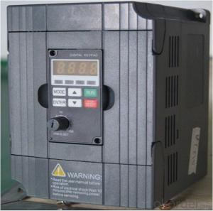
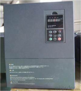
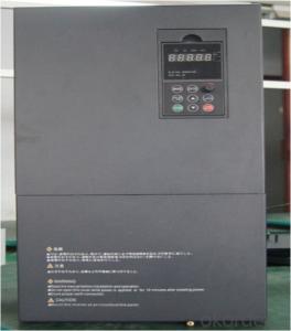
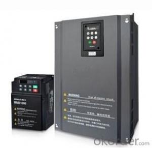
AC Driver China Best Selling VFD Variable Frequency Drive 3 phase 380V
- Ref Price:
-

- Loading Port:
- Tianjin
- Payment Terms:
- TT OR LC
- Min Order Qty:
- 1 pc
- Supply Capability:
- 100000 pc/month
OKorder Service Pledge
OKorder Financial Service
You Might Also Like

Specifications
1.220V Single Phase Variable Frequency Drive 2.2KW
2.Advanced control technology
3.Easy to operate
220V Single Phase Variable Frequency Drive 2.2KW
General
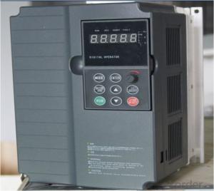
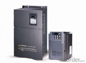
CNBM frequency inverter is a high-quality, multi-function,
low-noise variable frequency drive which is designed, developed and manufactured according to international standards.
It can meet different needs of industrial conditions.
The inverter applies advanced control technology of space voltage vector PWM, with functions of constant voltage control, power-off restart, dead zone compensation, automatic torque compensation, online modification parameter, high-speed impulse input, simple PLC and traverse.
Product Name:CMAX-VCG15/P18.5T3 ~ CMAX-VCG18.5/P22T3
Application
Textile: coarse spinner, spinning frame, wrap-knitting machine, loom, knitting machine, silk-spinning machine, etc.
Plastic: extruder, hauling machine, decorating machine, etc.
Pharmacy: mixer, roaster, etc.
Woodworking: engraving machine, sander, veneer peeling lathe, etc.
Papermaking: single type papermaking machine, etc.
Machine tool: non-core grinding machine, optical lens grinding machine, cutting mill, etc.
Printing: cloth-washing machine, dye vat, etc.
Cement: feeder, air blower, rotary furnace, mixer, crusher, etc
Fan and pump: kinds of fans, blowers and pumps
Specification
Item | Specification | |
Input | Input voltage | 220/380V±15% |
Input frequency | 47~63Hz | |
Output | Output voltage | 0~input voltage |
Output frequency | 0~600Hz | |
Peripheral interface characteristics | Programmable digital input | 4 switch input, 1 high-speed impulse input |
Programmable analog input | AI1: 0~10V input AI2: 0~10V input or 0~20mA input, | |
Programmable open collector output | 2 Output (3.7kW and above: 1 Open collector output) | |
Relay Output | 1 Output (3.7kW and above: 2 Relay output) | |
Analog output | 2 Output, one is 0~10V, another is 0~20mA or 0~10V | |
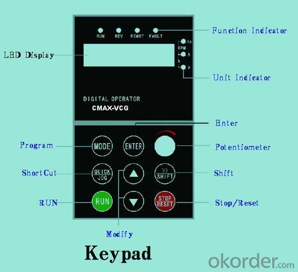
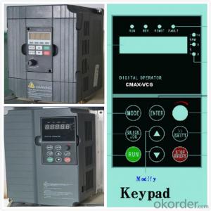
Keypad | Display:5-digit 8-section LED (Red), 2 indicators; parameter setting: 8 keys (including multi-function hot key ), 1 potentiometer | |
Technical performance characteristics | Control mode | All digital space voltage vector SVPWM algorism |
Overload capacity | G purpose: 150% rated current 60s P purpose: 120% rated current 60s | |
Speed ratio | 1: 100 | |
Carrier frequency | 1.0~10.0kHz | |
Torque compensation | Linear, multi-point, 1.3th power, 1.7th power, 2.0th power reduced torque; Compensation voltage range: automatic compensation and manual compensation 0.1~10% | |
Automatic voltage adjustment | It can automatically maintain output voltage constant when grid voltage fluctuates. | |
Automatic current adjustment | When the current is over current limit, under clocking automatically limits output current. | |
Function characteristics | Frequency setting mode | Keypad digital analog input, keypad potentiometer, impulse frequency, communication, multi-step speed and simple PLC, PID setting and so on, switch-over of setting modes. |
Simple PLC, multi-step speed control | 16-step speed control | |
Special function | Traverse control, length control, time control | |
QUICK/JOG key | User-defined multi-function hot key | |
Protection function | Over-current, Over voltage, under-voltage, over-heat, phase failure, over-load and motor over-load | |
Working condition | Installation site | Indoor, altitude of less than 1km, dust free, non-corrosive gases, no direct sunlight |
Application environment | -10°C~+40°C, 20~90%RH (no dew) | |
Vibration | Less than 0.5g | |
Storage temperature | -25°C~+65°C | |
Installation type | Wall-mounted type, floor cabinet type | |
Cooling mode | Air-forced cooling | |
- Q:Check the fault information is the power supply voltage instability, but other inverters are running well, what is the matter? Will there be any other parameters are not set correctly, thank you!
- To solve the problem, then check the original power of the line is loose, the power cables are quickly burnt, after fastening normal, thank you enthusiastic support, thank you!
- Q:At the base block Yaskawa inverter is what reason?
- This is the base block command, when the external input block command signal, the frequency converter will appear this code, the emergence of this code, the motor will rotate freely, does not affect the use.
- Q:How to deal with the fault Yaskawa inverter GF
- See the Yaskawa inverter protection circuit structure, and the other is the same frequency. Over current OL1, OL2 and OL3 fault signals should be current transformers and subsequent current detection and processing circuits and CPUThe fault signals of GF (ground) and OC (load side short circuit) shall be fed directly to the protection circuit of the drive circuit board to feed the CPU. The difference is that at the initial stage of the start-up, the detection module is abnormal, i.e., a fault is reported.If the module is detected in operation, the OC fault is reported. These two kinds of signals, but also revealed such a message: the initial stage, it has not yet established the three-phase output voltage, the load is not running, the actual fault sources should be inverter driving circuit or the IGBT module itself caused by the abnormal, but does not rule out a ground fault load;In operation, there is a very large current, jump OC, the load side of the probability of failure is large, but also over current fault, rather than ground fault. The difference between GF and OC faults and what they mean is really reasonable.
- Q:What does a frequency converter do?
- What is the starting current and starting torque of the motor when the inverter is in operation?Using frequency converter operation, with the acceleration of the motor, accordingly improve the frequency and voltage, the starting current is limited to 150% rated current (according to the type of machine is 125%~200%). The starting current is 6~7 times of direct starting with the mains frequency power supply, so the mechanical and electrical impact will be produced. It can start smoothly with frequency converter (longer starting time). The starting current is 1.2~1.5 times the rated current, the starting torque is 70%~120%, the rated torque; for the inverter with automatic torque enhancement, the starting torque is above 100%, and the full load can start.
- Q:The difference between soft starter and converter
- The inside of the inverter power module is IGBT, suitable for long time operation of the motor frequency; and the soft start most with the SCR by setting the interface to set the start time and the initial voltage and other parameters, once the completion of shipment immediately after the trip (to power) soft start circuit, bypass contactor, access frequency operation.
- Q:First of all, I would like to achieve the frequency converter with motor static linear acceleration, high-speed linear deceleration stop processFirst question: I say kind of situation, three paragraph speed start, 0.1hz---> high 30hz-->0.1hzSecond problem: manual speed instruction 1, speed 2, speed 3 instruction instruction I want to use PLC to control three speed motor with three reverse contact dry. I understand speed instruction 1 is switched on (2, 3 connected) transmission section set the frequency with the frequency segment set 0HZ123 AssociationThird questions: manual section, speed command, main frequency and STEP1-STEP7 stage setting frequency, I use PLC analog to the frequency main frequency setting, plus and deceleration, STEP1-7 are set 0, can achieve what I wantInitial contact frequency converter, home pointing
- Using PLC to analog converter control input frequency up to speed off from the requirements of the inverter frequency source set P-00 speed by 00 digital operation panel to analog frequency PLC given 0102 given frequency parameters can choose the set of 01 or 02 and the period of quick closing even P-17P-19 parameters affect analog control
- Q:Knowledge, principle and operation method of frequency converter.
- The three major parts of the working principle of frequency converter:This is how the inverter works, but how does it work? Mainly composed of three components. (1) convert the power frequency power to the rectifier of the DC power: it transforms the power frequency power into the DC power supply. A reversible converter can also be constructed using two sets of transistor converters, which can be regenerated for their reversible power direction. (2) absorption in the converter and inverter voltage generated by the pulsating "flat wave circuit" in the rectifier DC voltage is rectified, ripple voltage with power frequency 6 times, in addition the pulsating current generated by the inverter to the DC voltage fluctuation. (3) the DC power conversion for AC power rectifier with "inverter": instead, the inverter is DC power converter for AC power required frequency, to the time the 6 switch off, you can get 3 phase AC output.
- Q:Schneider 303 4KW frequency converter F 013 trouble shooting method
- If the converter is overloaded, it is recommended to check the set acceleration time and whether the load is blocked or not.
- Q:Where is the difference between soft starter and converter?
- The soft starter changes the supply voltage only and is equivalent to a step-down starter. The frequency converter is much more complex and much more expensive than the soft starter. The inverter also has a soft start function, which is achieved by changing the power frequency. Difference between high voltage starter and low voltage starterThe main circuit of the soft starter is thyristor, and the start-up process is completed by gradually changing the turn-on angle of the thyristor. This is the basic principle of the soft starter. In the low-voltage soft starter market, a wide range of products, but high voltage soft starter products are still relatively small. High voltage soft starter is the same as low voltage soft starter, but there are some particularities in high voltage soft starter and low voltage soft starter:
- Q:Why does the frequency converter cause interference?
- (a) PE converter main circuit terminals (E, G) must be grounded, the motor can be grounded and the inverter with the common ground, but not with other equipment, must play ground pile, and the ground should take place far away from electrical equipment. At the same time, the cross-sectional area of the grounding wire of the converter shall be no less than 4mm2, and the length shall be within 20m.(b) in the ground wire of other electromechanical equipment, the protective earthing and the work earthing shall be separately provided with grounding electrodes, and finally shall be imported to the electrical position of the distribution cabinet. The shield of the control signal and the shielding of the main circuit wire shall also be separately provided with earth electrodes, and finally shall be incorporated into the electrical junction of the distribution cabinet.
1. Manufacturer Overview |
|
|---|---|
| Location | |
| Year Established | |
| Annual Output Value | |
| Main Markets | |
| Company Certifications | |
2. Manufacturer Certificates |
|
|---|---|
| a) Certification Name | |
| Range | |
| Reference | |
| Validity Period | |
3. Manufacturer Capability |
|
|---|---|
| a)Trade Capacity | |
| Nearest Port | |
| Export Percentage | |
| No.of Employees in Trade Department | |
| Language Spoken: | |
| b)Factory Information | |
| Factory Size: | |
| No. of Production Lines | |
| Contract Manufacturing | |
| Product Price Range | |
Send your message to us
AC Driver China Best Selling VFD Variable Frequency Drive 3 phase 380V
- Ref Price:
-
- Loading Port:
- Tianjin
- Payment Terms:
- TT OR LC
- Min Order Qty:
- 1 pc
- Supply Capability:
- 100000 pc/month
OKorder Service Pledge
OKorder Financial Service
Similar products
New products


Hot products

Hot Searches
Related keywords

