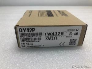

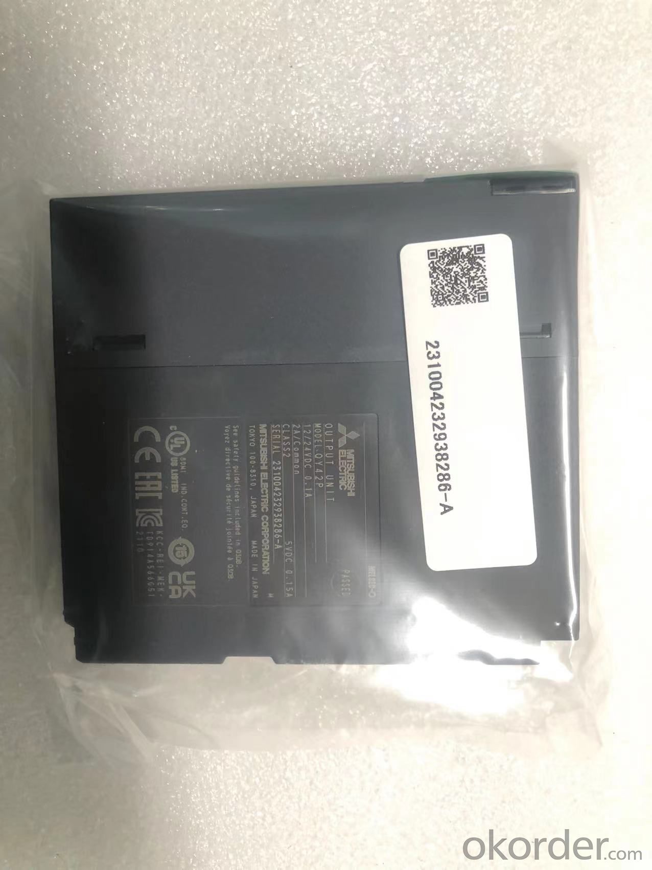
Q Series 64 Point Output Module QY42P Mitsubishi Model Transistor Drain Type
- Ref Price:
-

- Loading Port:
- Shekou
- Payment Terms:
- TT OR LC
- Min Order Qty:
- 1 kg
- Supply Capability:
- 1200 kg/month
OKorder Service Pledge
OKorder Financial Service
You Might Also Like
Item specifice
Specification of Mitsubishi q series output module qy42p:
[output type] transistor drain output module
[output points] 64 points
[isolation method] Optocoupler
[rated load voltage] 12-24vdc (+ 20 / - 15%)
[maximum load current] 0.1a/point, 1.6a/common terminal
[maximum starting current] 0.7A, 10ms or less
[leakage current at off] 0.1mA or less
[maximum voltage drop at on] 0.1vdc (standard) 0.1A, 0.2vdc (maximum) 0.1A
[on - > off response time] 1ms or less
[off - > on response time] 1ms or less (rated load, resistive load)
Zener diode
[fuse] none
[external power supply voltage] 12-24vdc (+ 20 / - 15%) (ripple coefficient
within 5%)
[external power supply current] 20mA (at 24VDC) / common terminal
[dielectric withstand voltage] 560vacms / 3 cycles (altitude 2000m (6557.38
feet))
[insulation resistance] 10m Ω or higher measured by insulation resistance
tester
[immunity] through 1500vp-p noise voltage, 1 μ Voice simulator with s voice
width and 25 to 60Hz voice frequency
First instantaneous voice iec61000-4-4: 1kV
[protection grade] IP2X
[common terminal arrangement] 32 points / common end (common end: 1a01, 1a01,
2a01, 2A02)
[I / O points] 64 (set the I / O allocation according to the 64 point output
module.)
[overheat / short-circuit protection function is activated in [with] increment
[running indicator] on indication (LED)
[external connection] 40 pin connector * 2 rows
[applicable wire diameter] cable core: 0.3mm2 (for a6con1)
[external wiring connector] a6con1, a6con2, a6con3 (optional)
[connector / terminal converter] a6tbxy36, a6tbxy54
[5VDC internal current consumption] 105ma (standard: all points on)
[overall dimension h * w * D] 98 * 27.4 * 90mm
[weight] 0.17kg
- Q:If not, and if I have to put a 5 wire connector on the truck, where does the blue wire connect?
- you will have to run a trailer brake controller for 5 wireno adapter for this. The feed from the controller can't be shared with any of the other funtions.ex. tail lights, brakes lights, ect. I wouldn't go for a 5 wire. Just go straight to a 7 way plug that has every thing. A blue wire is usally 90% of the time the standard colour for a brake controller wire. I know that is how my plug is wired. And buy the way, a good 7 way plug has the colours marked on the back of it to show you where to put the wires by colour. Last two cents here, you can buy a 4 wire adapter for a 7 way plug. Always easier to go down then try to put one more then what you need. hope this helps and isn't to confusing .
- Q:I have 1 red and 2 yellow composite connectors on my tv, Roku requires 1 red, 1 yellow and 1 white connector. Do you think just yellow and red would work? any suggestions? Thanks
- REALLY ODD: Could be one of two things. 1) That the connectors are miss labeled. In that case, plug red -red, and then try to plug the yellow and white into the two yellow. If that doesn't work reverse the white / yellow. 2) The TV is mono. In that case, plug in one the red and yellow connectors. Just to break it down for you: Red / White - are left and right audio Yellow - video - 17R3W
- Q:I have a pdx 1.1000 amplifier and the PREOUT Input RCA terminal is broken and I cannot get it fit right. I've tried everything, please don't tell me how I can fix this connector. I just want to know if I can solder the RCA connector to the metal part of the terminal. Not the gold plated one, but the 2 little prongs sticking out on both sides and with the gab in the middle that goes down into the board.
- If you're good at soldering yes but be careful, you need to get a good connection I've done it on a home reciever before
- Q:i just bought a new psu from tiger direct and hooked it all up come to find out that my mother board has a p4-mb connection slot but the power supply doesnt have any 4 pin connectors how can i solve this problem do i need a different psu?
- Recent and current ATX power supplies HAVE the 4 or 8-pin (4+4) 12V power connector to motherboard. The connector has yellow and black wires. The 8-pin connector usually breaks into two. Just use the half 4-pin connector.
- Q:CAN ANYBODY PLEASE GIVE AN EXAMPLE OF A U.H.F. CONNECTOR????Also kindly advise me on how can I reduce impedance losses while connecting a coaxial cable between a source and a load through connectors. Like a 50 MHz source and 50 MHz load impedance matching might suffer losses due to dielectrics(male-female air gap), resistance, etc.PLEASE PLEASE DO ANSWER.I URGENTLY NEED THE ANSWER.LOTS OF THANX IN ADVANCE
- Type N connector is one of the best, good to 11 GHz, so it will handle 440 MHz with no problems. For 50 MHz, most any coax connecter will be fine. At 440 MHz, you have to be a bit more picky, but most good ones will work well. The second reference has a list of RF connectors. A BNC connector is very common and is good to 2 GHz. Note that although a connector type can be used to 2 GHz, for example, that does not mean that it is a perfect impedance with no reflections. BNC for example, is not great and has high reflections. Whereas type N is much better, and can also handle more power. As to your question, you need to be more specific. What exactly do you want? UHF Connector at 437 MHz mean what? Most any coax connector will work at that frequency, the question is how well. .
- Q:I recently took the Hitachi hard drive out of my Pavilion dv9000 that I bought in 2007, and it has the strangest connectors I've ever seen. I can't tell if i'ts IDE or SATA; it doesn't use pins, per se, but blades.
- It's proprietary, so you need to buy from HP.
- Q:Hello. I have XP SP3 installed just to let you all know. I am trying to get my Nintendo Wii to receive an internet signal via my Nintendo Wi-Fi USB Connector. Here's the thing. I have set my firewall setting to allow access from every Nintendo related thing installed on my PC, but it STILL will not let the USB connect to the Wii, to get a signal. When I turn off the firewall, the Wii will receive the signal no problem. I've never had a problem like this before. When I first installed the USB, it worked perfectly! Don't tell me to reinstall the software, tried like 10 times! Anybody know what's going on? Thx for serious answers!
- It's because the Nintendo Wi-Fi Connector cannot get through the firewall even if you have allowed your computer to let it through. The connector will only work if the firewall is turned fully off. This happened to mine and it would only work when the firewall was off. But, it shouldn't be a problem to your PC if you just keep the firewall off only while you are playing on-line. When you are not playing on-line, just turn the firewall back on.
- Q:I have an Rio EP and was wondering if i could switch the connectors for Traxxas ones and run them in parallel? Thank you.
- If you look up on the forums there are how tos on wiring,soldering,parallel etc.Hobbyking,Hobbytron others have forums also for lipo,lfe,deans,bullet connectors wiring and alot more.I found my batteries and connectors along with people who have wired parallel and high amp discharge batteries on hobbyking forums,and prices are awesome.Good Luck!
- Q:Does anyone know where the OBD connector is located on this model?
- 16 pin connector that is wider on one side that the other, located underneath the edge of the dash between the right hand side of the steering wheel and the drivers side end of the dash
- Q:for a vidoe camera
- DVI or Digital Visual Interface was introduced in 1999. They are found on all flat panels monitors and TV's ,DVD players , Data projectors, and cable set top boxes. Shortly after its introduction, it rapidly became the industry standard for digital interfaces. DVI supports high bandwidth Digital content Protection HDCP. During the transition phase from analog to digital, most monitors and displays came with both a DVI and A VGA connector. The DVI connections accept both formats by using a DVD-A plug or a DVD-D plug for the respective format. Single link DVI supports resolution up to 1920 by 1080 at 60 hertz. For higher resolutions a dual DVI configuration is deployed, which can provide for resolution as high as 2560 x 1600 at 85 hertz.
1. Manufacturer Overview |
|
|---|---|
| Location | |
| Year Established | |
| Annual Output Value | |
| Main Markets | |
| Company Certifications | |
2. Manufacturer Certificates |
|
|---|---|
| a) Certification Name | |
| Range | |
| Reference | |
| Validity Period | |
3. Manufacturer Capability |
|
|---|---|
| a)Trade Capacity | |
| Nearest Port | |
| Export Percentage | |
| No.of Employees in Trade Department | |
| Language Spoken: | |
| b)Factory Information | |
| Factory Size: | |
| No. of Production Lines | |
| Contract Manufacturing | |
| Product Price Range | |
Send your message to us
Q Series 64 Point Output Module QY42P Mitsubishi Model Transistor Drain Type
- Ref Price:
-
- Loading Port:
- Shekou
- Payment Terms:
- TT OR LC
- Min Order Qty:
- 1 kg
- Supply Capability:
- 1200 kg/month
OKorder Service Pledge
OKorder Financial Service
Similar products

New products
Hot products
Related keywords

