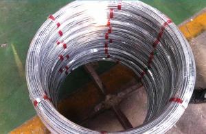
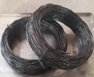
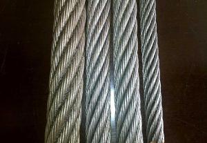
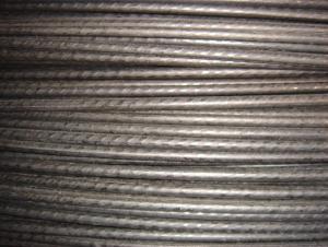
Class B Zinc Layer Of Electro Galvanized Wire
- Ref Price:
-

- Loading Port:
- China Main Port
- Payment Terms:
- TT OR LC
- Min Order Qty:
- -
- Supply Capability:
- -
OKorder Service Pledge
OKorder Financial Service
You Might Also Like


、
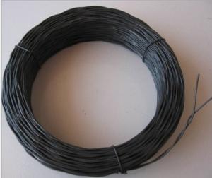
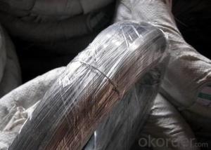
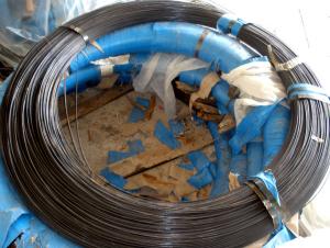
Packaging & Delivery
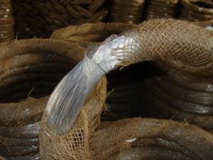
| Packaging Detail: | 1. Inside with plastic film, outside weaving bag. 2. Inside with plastic film, outside hessian cloth. |
| Delivery Detail: | 15~30 days |
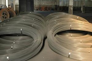
Specifications
1. Material is Q195(C is 0.06% ~ 0.12%)
2. Zinc coating is 40/m2 ~ 60g/m2
3. Tensile strength is 400N ~ 600N
Hot-Dip Zinc-Plating Iron Wire
Material: super carbon steel Processing by drawing, hot-dip zinc-plating Standard wire gauge from 8# to 24# Thick zinc-coating layer Super in corrosion resistance Firm coating layer Custom size available
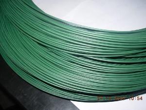
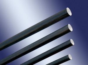
Hot dipped galvanized wire and Electro galvanized wire | |
Metric system | British System |
4.0mm-0.30mm | BWG8-BWG30 |
Tensile strength: 30-55kg/mm2 | |
Zinc coating: 20-32g/m2 6-295g/m2 | |
Packing: inside polyethylene film, outside PVC film or hessian cloth | |
- Q:And if anyone could give me percise instructions on wiring subs to 1 or 4 ohm that would be great. I have two dual 4 ohm subs and need to know how to solder wires or crimp wires.
- really pretty simple.you can buy a cheap soldering iron for about eight bucks at walmart that comes with solder.plug the iron in and let it heat for about four to five minutes.while waiting on it to heat up twist the wires together.once the iron is hot put it on the wires and heat them for about thirty seconds.once they are hot put the solder on the wires and it will start to melt .use they iron to spread the solder over wires.it will be bonded and your ready to go.
- Q:A 41.7-kg sign is suspended by two wires, as the drawing shows. Wire 1 makes and angle of 42.2deg with the horizontal and wire 2 makes an angle of 58.8deg. Find the tension in wire 1 and wire 2.
- To solve this, you have to find 2 equations, because there are 2 unknowns. Assume, Tension in wire 1 = T1 Vertical component of T1 = T1 sin42.2 Horizontal component of T1 = T1 cos42.2 Tension in wire 2 = T2 Vertical component of T2 = T2 sin58.8 Horizontal component of T2 = T2 cos58.8 Since the sign board is in equilibrium, the forces must balance each other. Horizontally, the horizontal components of both forces are balancing each other. Therefore, T2 cos58.8 = T1 cos42.2 T2 = (T1 cos42.2) / (cos58.8) -------------------(1) For the vertical components of the wire, both are balancing the weight of the sign. T1 sin42.2 + T2 sin58.8 = (41.7)(9.8) T1 sin42.2 + T2 sin58.8 = 408.66N ----------------(2) Combine (1) into (2), T1 sin42.2 + (T1 cos42.2)(sin58.8) / (cos58.8) = 408.66 T1 ( sin 42.2 + cos 42.2 tan 58.8) = 408.66 T1 = 215.66N Subst T1 = 215.66N into (1), T2 = (T1 cos42.2) / (cos58.8) = 308.4N Hope it is correct ^^
- Q:I would like to know how to wire my West Marine VHF Radio.Coming out the back of the radio is a red wire, a white wire, and two black wires. The white wire and one of the black wires are a thinner gauge then the other black and red wires. Any solutions out there? Thanks
- You could solder (best), or crimp connect a waterproof In Line fuse to the red wire, then connect it to a terminal Ring, and put over the red + battery post, then ground the black wire, by connecting a Terminal ring to it and put it over the NEG.- battery post. The In-Line fuse is circuit protection, OR you can by-pass this by conecting to a spare fuse on the Panel (red +), then ground the black wire to the Neg on the battery or neg - on the panel (fuse block). Direct connection to the battery is best, the other wires probably go to the Aux. Speaker which you will need as the speakers on the radio are too small to be heard over engine noise. Soldering works BEST, then coat with Liquid Lectric tape, or heat shrink tubing for a water resistant seal on the wires, and a good Marine connection. E-mail is open if further assistance is needed.
- Q:I dont understand it I am trying to get a 1ohm load on a 2ohm dvc speaker but cant figure out how to tell if the wire you connect in the postive terminal on the sub in a neg wire or positive how do you tell what the gray line is on this diagram positive or negetive and how to tell. thanks
- You are wiring the sub in parallel. from the positive terminal of the amp you connect both positive terminals of the sub, and Viceversa for the negative. The wire is either positive or negative depending on which terminal it touched. Make sure your amp can handle an impedance of 1 ohm.
- Q:Consider a copper wire 1 mm in diameter providing the power needed to run an appliance drawing a 4.8 kW at 12 V. Assuming that no heat is radiated away from the wire while the current flows:A. What will the temperature of the wire be after the current has run for 1 second through the wire?B. What will the physical condition of the wire be at that time?(The wire was initially at 20 degrees C)
- Assume the wire is 1 meter long. Resistance of a wire in Ω R = ρL/A ρ is resistivity of the material in Ω-m L is length in meters A is cross-sectional area in m? A = πr?, r is radius of wire in m resistivity Cu 17.2e-9 Ω-m or 17.2e-6 ohm-mm R = (17.2e-6)(1000) / π(0.5)? = 0.022 ohms Appliance current is 4800/12 = 400 amps Power is I?R = 400? x .022 = 3520 watts. Problem, this power is at a level almost as high as that of the appliance. In other words, the wire is too thin to sustain that power level. .
- Q:Currently I have the two wires no ground wire and some two wire with ground outlets (upgrade some time before). Is it allowed in the NEC to run a separate ground wire from one of the two wire with ground outlet to the two wire outlet without changing the old wires?
- It isn't allowed to ground the new 'grounding' receptacle to another receptacle on another circuit (if that is what you are asking) Other than that, it IS allowed to be grounded to an accessible point on the grounding electrode system (metal cold water pipe or wire connected to it), the system grounding electrode (ground rod, etc.), the ground bar in the panel from which that circuit originates, or the grounded conductor bar in the panel which the circuit originates (neutral bar). The only other legal option is to install a GFI and label it No Equipment Ground. You can connect downstream receptacles to that same GFI, but cannot connect a ground wire from the GFI to any downstream receptacles and they too must be marked No Equipment Ground and GFCI Protected. The way a GFI works is quite simple. If the current on the hot and neutral conductors isn't the same (within 5mA), it trips. So if there is a different path from hot to anything other than neutral, it will trip.
- Q:I'm trying to install a ceiling fan but I'm having trouble with the wiring. Coming out of the fan I've got a black, white, black and white striped, and a green wire. coming out of the cieling i've got a black, a white and a red wire.The fan's green wire is connected to the bracket as a ground, so that's out of the way. It's the other wires that confuse me. I've tried, white to white, black to black, and BW striped to red, but that didn't do anything.Any ideas? Thanks.
- Be careful when with just hooking Black to Black or White to White as has been suggested. In some configurations the white wire is part of the switch leg and is not nuetral. Being that this is a 50 year old house, the Hot wire from the breaker box could very possibly be coming in at the light box instead of the switch box which would mean that there is a wire that is using both the Black and the White wires for power. One of them is taking power to the switch and the other is bringing power back to the light from the switch when the switch is turned on. In this scenario, the white wire would not be nuetral!!! The brown wire was typicallly used for hot up into the 70's and then they changed it to black. Your best bet is to hook it up exactly the way you took it off and hook the Blue and Black wire from your fan to the same wire. I assume that this fan has pull chain controls for both the light and the fan?.....
- Q:exact wiring
- 1995-96 Dodge Dakota Alarm, Remote Starter, Keyless Entry Wiring Information Constant 12V+ Pink/Black Ignition Switch Harness Starter Yellow Ignition Switch Harness Ignition Dark Blue Ignition Switch Harness Ignition 2 Black Ignition Switch Harness Accessory Black/Orange Ignition Switch Harness Tach Gray Coil Neutral Safety Wire Brown/Yellow Driver's Side of Trans. Brake Switch White or White/Tan Brake Switch Trunk Pin n/a Parking Lights Black/Yellow Light Switch Head Lamp Light Green Light Switch Hood Pin n/a Door Trigger Yellow (-) Driver's Pin Switch Door Lock Orange/Purple Driver's Kick Panel Door Unlock Pink/Purple Reverse Polarity Horn Wire Dark Green/Red (-) Fuse Panel Windows Up LF=Light Blue, RF=Brown/White Windows Down LF=White, RF=Purple/White
- Q:i am hooking up a wiring harness on a 2000 ford ranger and cant figure out the wires to hook up and what they are
- you need to buy the harness for that particular truck, there's a plug already there for it, if you start hacking into wires you'll have more problems than you can believe. and I'm not going to explain it here, just trust me, there like $20 bucks and will save you a world of headaches.
- Q:Hello, i am trying to hook up power windows in my truck. the motor has two wires and the switch has 3 wires. i just need the relay. i just need to know what kind of relay i need and how to hook it up. i know i need a reversing relay and that it needs to use the 3 switch wires along with the two motor wires and the two power wires. does anyone know what this relay is called and where i could find it online? thank you.
- Hold your horses here as this gets real complicated real fast Motor has two wires one is pos and the other is neg on the down stroke. Reverse applies on the up stroke. Three wires from switch. Center is supply (either ground or 12 v.d.c) Other two are outputs from the supply. (ground is suggested) There are literally 50 different relay types you can use depending on the application. Some are three pin some are four pin and some are five pin. The five pin is the most common type used for power windows. I suggest going to the local junk yard and find a ford F series truck with fuel injection Open hood and look on drivers inner fender well on back side of air filter box. There will be two or three relays under a small plastic cover mounted on slip mounts and if you pull up hard enough they will come off. Cut the wires to these relays as far back towards the dash as you possibly can (to get the most wire possible) You will need two of them per window. These are the commonly sold five pin relays and once you have them then e-mail me through my avatar and I can direct you exactly what wire to what pin to what wire on switch and then to motors.
1. Manufacturer Overview |
|
|---|---|
| Location | |
| Year Established | |
| Annual Output Value | |
| Main Markets | |
| Company Certifications | |
2. Manufacturer Certificates |
|
|---|---|
| a) Certification Name | |
| Range | |
| Reference | |
| Validity Period | |
3. Manufacturer Capability |
|
|---|---|
| a)Trade Capacity | |
| Nearest Port | |
| Export Percentage | |
| No.of Employees in Trade Department | |
| Language Spoken: | |
| b)Factory Information | |
| Factory Size: | |
| No. of Production Lines | |
| Contract Manufacturing | |
| Product Price Range | |
Send your message to us
Class B Zinc Layer Of Electro Galvanized Wire
- Ref Price:
-
- Loading Port:
- China Main Port
- Payment Terms:
- TT OR LC
- Min Order Qty:
- -
- Supply Capability:
- -
OKorder Service Pledge
OKorder Financial Service
Similar products
New products

Hot products