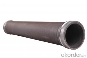

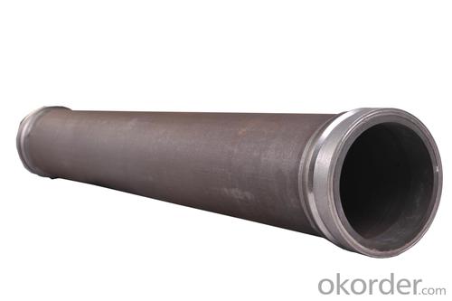
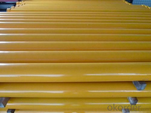
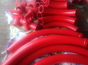
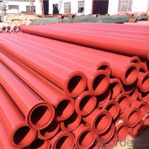
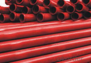
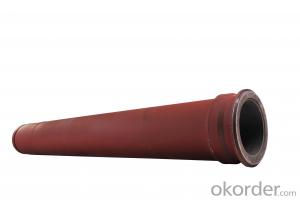
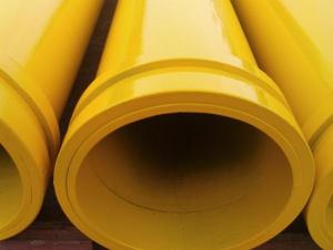
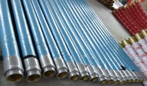
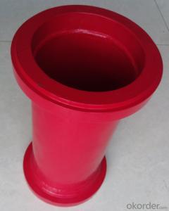
Twin Wall Pipe for Concrete Pump Pipe Thickness 7mm Length 2000mm
- Ref Price:
-

- Loading Port:
- Tianjin
- Payment Terms:
- TT OR LC
- Min Order Qty:
- 50 pc
- Supply Capability:
- 2000 pc/month
OKorder Service Pledge
OKorder Financial Service
You Might Also Like
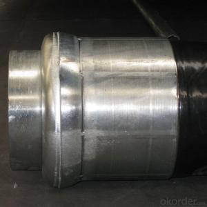
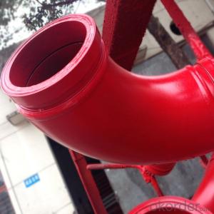
1. Diameter: DN125
2. Wall thickness: inner wall is 4 mm 65Mn, outer wall is 3mm seamless steel
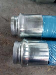
3. Length: 3000&2000&1000mm with wear resistant SK flange
4. Type: Double / twin wall
5. Hardness: HRC 63
6. Using life: 60,000-100,000(CBM)
7. Highlights: longest using life
8. Welding: Smooth welding between straight pipes and flanges
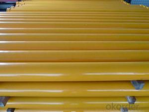
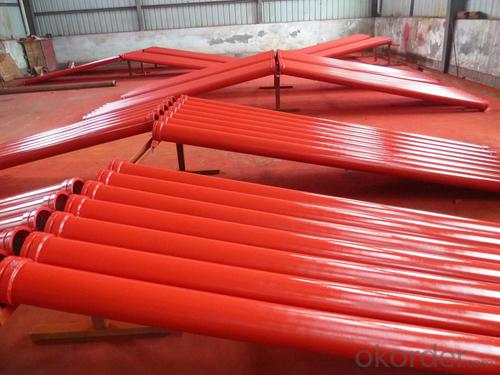
9. Color : as customer's requirement,usually bule or red
10. Surface: Electrostatic Spraying Epoxy Paint
11. Packing: Wrapped by water proof poly-bag to protect the
painting and flanges & seaworthy
or according to customers’ requirements.


- Q: What are the signs of a malfunctioning hydraulic oil cooler?
- There are several signs that can indicate a malfunctioning hydraulic oil cooler. 1. Overheating: One of the most common signs is the engine or hydraulic system overheating. If the hydraulic oil cooler is not functioning properly, it may not be able to cool down the hydraulic fluid effectively, leading to increased temperatures in the system. This can result in reduced performance, increased wear and tear on components, and potential fluid breakdown. 2. Fluid Leaks: Another sign is the presence of hydraulic fluid leaks. A malfunctioning hydraulic oil cooler may have damaged or worn seals, gaskets, or hoses that can cause leaks. These leaks can be visible as fluid drips or puddles underneath the machinery or as oily residue on components. 3. Increased Noise: A malfunctioning hydraulic oil cooler may also cause increased noise levels in the hydraulic system. This can be due to air being introduced into the system, resulting in cavitation or aeration. These abnormal noises can indicate that the cooler is not functioning properly and may need to be inspected or replaced. 4. Elevated Temperatures: If you notice that the temperature gauge on your hydraulic system is consistently higher than normal, it could be a sign of a malfunctioning oil cooler. The cooler may not be able to effectively dissipate heat from the hydraulic fluid, causing temperatures to rise. This can lead to reduced efficiency, increased wear on components, and potential system failures. 5. Reduced Performance: A malfunctioning hydraulic oil cooler can also lead to reduced overall performance of the machinery or equipment. This can manifest as slower operation, decreased power output, or reduced hydraulic system response. If you notice a decrease in performance, it is worth checking the oil cooler for any issues. If you observe any of these signs, it is important to address the issue promptly. Continuing to operate machinery with a malfunctioning hydraulic oil cooler can lead to further damage, increased downtime, and potentially costly repairs. Consulting with a qualified technician or hydraulic specialist is recommended to diagnose and resolve any issues with the oil cooler.
- Q: How often should concrete pump accumulators be inspected and replaced?
- To ensure proper functioning and prevent potential issues, it is important to regularly inspect concrete pump accumulators. The frequency of inspections will depend on factors such as manufacturer recommendations, usage intensity, and operating conditions. As a general rule, it is recommended to inspect the accumulators at least every six months or after every 500 hours of operation, whichever comes first. However, if the pump is used more frequently or operates under harsh conditions, more frequent inspections may be necessary. During the inspection, check the accumulators for visible signs of wear or damage, such as leaks, cracks, or corrosion. Additionally, test the pressure levels and performance to ensure they meet the required standards. When it is time for replacement, it is best to follow the manufacturer's recommendations. Typically, accumulators have a lifespan of around 3 to 5 years, but this can vary based on maintenance, usage, and environmental conditions. If any significant issues are found during the inspection or if the accumulators have reached their recommended lifespan, it is advisable to promptly replace them to avoid potential failures and ensure the safety and efficiency of the concrete pump.
- Q: How does a concrete pump S valve function?
- Controlling the flow of concrete from the hopper to the discharge outlet is the primary function of the S valve in a concrete pump. This valve is a critical component in the concrete pumping system, enabling the accurate and efficient delivery of concrete to the intended destination. The S valve comprises two distinct valves, one on each side, connected by a central shaft. These valves are shaped like the letter "S," hence the name. Each valve possesses a concrete outlet and a hydraulic cylinder that governs its movement. When the concrete pump is activated, the hydraulic system exerts pressure on the cylinders, causing them to extend and open the valves. This opening enables the flow of concrete from the hopper into the pump's cylinder. Once the concrete enters the cylinder, the hydraulic system reverses the pressure on the cylinders, prompting them to retract. This retraction movement closes the valves, effectively sealing the cylinder and preventing any concrete from flowing backward. As the cylinder retracts, it propels the concrete towards the discharge outlet. The pressure generated by the cylinder's retraction forces the concrete through the outlet pipe, directing it to the desired pouring location. The ingenious design of the S valve ensures a seamless and uninterrupted flow of concrete, eliminating any potential interruptions or obstructions. Moreover, it grants operators a high level of control over the concrete placement, enabling them to adjust the flow rate and direction according to their requirements. In conclusion, the concrete pump S valve assumes the crucial role of regulating the concrete flow, guaranteeing its efficient and precise delivery to the intended destination. Its dependable and effective operation is indispensable for the success of concrete pumping operations.
- Q: Can I get spare parts for concrete pump hopper agitators and vibrators?
- Yes, you can get spare parts for concrete pump hopper agitators and vibrators.
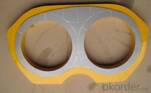
- Q: What is the role of a concrete pump spectacle plate?
- The main purpose of a concrete pump spectacle plate is to provide a stable and secure platform for the concrete pump to rest on while it is in operation. It serves as a support base for the pump, ensuring that it remains steady and balanced while it pumps concrete. The spectacle plate is typically constructed using durable materials like steel or alloy, which can withstand the weight and pressure exerted by the pump. Its design incorporates various features, such as slots or holes, which allow for the attachment of accessories like clamps or pipes. This facilitates a smooth and efficient transfer of concrete from the pump to the desired location. Additionally, the spectacle plate may also have adjustable elements that enable positioning and alignment adjustments, ensuring precise placement of the concrete. In summary, the spectacle plate is essential for maintaining the stability and functionality of the concrete pump, thereby contributing to the successful completion of construction projects.
- Q: How can a malfunctioning hydraulic motor affect the pumping process?
- Various negative effects can occur in the pumping process due to a hydraulic motor malfunction. Firstly, there may be a decrease in pumping efficiency. The hydraulic motor is responsible for converting hydraulic energy into mechanical energy, which drives the pumping mechanism. If the motor is not functioning properly, it may not generate enough power to operate the pumping system effectively, resulting in a decrease in the volume or pressure of the pumped fluid. Moreover, an increase in energy consumption can be caused by a faulty hydraulic motor. Inefficient or faulty motor operation can lead to higher energy requirements to maintain the desired pumping rate. This increased energy consumption can result in higher operating costs and reduced overall system performance. Furthermore, irregular pumping or complete pump failure can occur as a result of a malfunctioning hydraulic motor. If the motor is not operating correctly, it may cause intermittent or inconsistent pumping, leading to fluctuations in the flow rate or pressure of the pumped fluid. In extreme cases, the motor may stop working entirely, resulting in a total loss of pumping functionality. Additionally, the entire pumping system may experience increased wear and tear due to a malfunctioning hydraulic motor. Improper motor operation can create excessive vibration or heat, leading to premature failure of other components such as seals, bearings, or pistons. This can result in frequent maintenance or repair requirements, leading to increased downtime and costs. In summary, the pumping process can be significantly affected by a malfunctioning hydraulic motor. This includes decreased efficiency, increased energy consumption, irregular pumping or complete pump failure, and increased wear and tear on the system. It is essential to regularly inspect and maintain hydraulic motors to ensure proper functioning and avoid potential issues that may disrupt the pumping process.
- Q: What are the different types of concrete pump hydraulic filters?
- There are three main types of concrete pump hydraulic filters: suction filters, return line filters, and pressure line filters. Suction filters are located at the inlet of the pump and prevent debris from entering the system. Return line filters clean the hydraulic oil as it returns from the system back to the reservoir. Pressure line filters are installed in the discharge line and remove contaminants before the oil reaches the hydraulic components.
- Q: How do I properly adjust and control flow rates in concrete pump spare parts?
- To properly adjust and control flow rates in concrete pump spare parts, there are a few key steps to follow: 1. Understand the equipment: Familiarize yourself with the specific concrete pump spare parts you are working with. Read the user manual and refer to any documentation provided by the manufacturer. This will help you gain a comprehensive understanding of the equipment's capabilities and how to adjust flow rates effectively. 2. Check the pump settings: Before starting any concrete pumping operation, ensure that the pump settings are properly configured. This includes checking the hydraulic pressure, engine RPM, and any other relevant settings. Make sure all valves and controls are in the correct position for the desired flow rate. 3. Monitor the pump speed: The speed of the pump directly affects the flow rate of the concrete. Different concrete mixtures may require different pump speeds to achieve the desired flow rate. Adjust the engine RPM accordingly, referring to the manufacturer's recommendations and any specific requirements for the project. 4. Adjust the pump stroke: Most concrete pumps have adjustable pump strokes to control the flow rate. By changing the length of the stroke, you can increase or decrease the volume of concrete being pumped. Experiment with different stroke lengths to find the optimal flow rate for your specific application. 5. Use the control panel: Many concrete pumps come equipped with a control panel that allows for precise adjustment of flow rates. Take advantage of these features to fine-tune the flow rate. Use the control panel to monitor the pump's performance and make any necessary adjustments to maintain a consistent flow. 6. Regularly inspect and maintain the equipment: Proper maintenance is crucial to ensure the accurate adjustment and control of flow rates. Regularly inspect the concrete pump spare parts for any signs of wear or damage. Clean and lubricate the components as recommended by the manufacturer. A well-maintained pump will operate more efficiently and provide more accurate control over flow rates. By following these steps, you can properly adjust and control flow rates in concrete pump spare parts. Remember to always prioritize safety and consult the manufacturer's instructions and guidelines for specific recommendations and considerations.
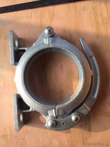
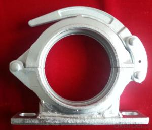
- Q: What is the function of a concrete pump hopper grate clamp?
- A concrete pump hopper grate clamp is a device used to secure the hopper grate in place on a concrete pump. The hopper grate is an essential component of the pump that acts as a filter to prevent large debris and foreign objects from entering the pump system. The clamp is designed to hold the hopper grate tightly in place, ensuring that it remains secure during the pumping process. By keeping the hopper grate in place, the clamp helps to maintain the integrity of the pump system and prevent any potential damage or blockages that could occur from the entry of unwanted materials. Overall, the function of a concrete pump hopper grate clamp is to provide a secure and reliable way to keep the hopper grate in place, allowing for smooth and efficient concrete pumping operations.
- Q: What are the indications of an inaccurate concrete pump pressure gauge?
- Some indications of an inaccurate concrete pump pressure gauge may include inconsistent readings, sudden drops or spikes in pressure, or when the gauge fails to return to zero when the pump is turned off.
Send your message to us
Twin Wall Pipe for Concrete Pump Pipe Thickness 7mm Length 2000mm
- Ref Price:
-
- Loading Port:
- Tianjin
- Payment Terms:
- TT OR LC
- Min Order Qty:
- 50 pc
- Supply Capability:
- 2000 pc/month
OKorder Service Pledge
OKorder Financial Service
Similar products
Hot products
Hot Searches
Related keywords

