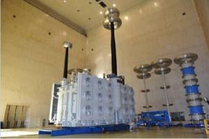

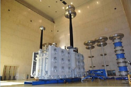
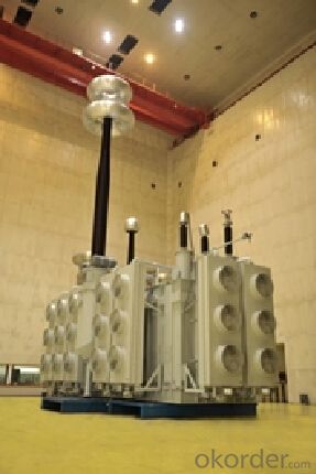
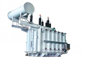
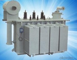
The world's first 1500MVA/1000kV UHV AC transformer
- Ref Price:
-

- Loading Port:
- Tianjin
- Payment Terms:
- TT OR LC
- Min Order Qty:
- 1 pc
- Supply Capability:
- 1 pc/month
OKorder Service Pledge
OKorder Financial Service
You Might Also Like


Quick Details
| Place of Origin: | HeBei | Brand Name: | CNBM | Model Number: | SFZ10-63000 / 110 |
| Usage: | Power | Phase: | Three | Coil Structure: | Toroidal |
| Coil Number: | 3 Winding | Capacity: | 50000 63000 80000 100000 120000 180000 | Rated Voltage: | 1000kV |
| Connection Symbol: | YNd11 Dyn11 YNyn0d11 | Tank: | Cover type or Bell type | OLTC: | MR or ABB or SMS |
Packaging & Delivery
| Packaging Detail: | Mainbody --naked Disassembled parts -- crate |
| Delivery Detail: | 3 months |
Specifications
1. CESI certificate
2. High short-circuit withstand
3. Low loss, PD and noise
4. CTQC certificate
5. No leakage
Description
The application of 1500MVA/1000kV AC UHV Transformer can significantly improve the economy of the UHV substation, and matches well with the transmission capacity of UHV lines, which has wide prospect of application. Because of its large capacity and large volume, the whole transportation weight with nitrogen is about 470-490 tons, and due to the restricted transport conditions, the transportation becomes the critical issue for application of the 1500MVA/1000kV UHV AC transformer. In order to make the products applicable to any UHV substation in our country, the state grid of corporation of China set the "A study of easy-transport large capacity UHV Transformer” as a key scientific research projects, and entrusted BTW to carry out the research.
During the process of research and development, BTW adopted the advanced design technology and modular design, the transformer can be transported disassembly and with advantages of compact core and winding body, less transportation weight and low transportation cost, effectively solves the need of UHV construction in the transportation restricted areas. By using the most advanced 3D magnetic field calculation software, BTW performed detailed analysis and calculation for the magnetic flux leakage and eddy current loss of the transformer coil, iron core and oil tank steel structures. Besides, by using of the advanced electric field calculation software, BTW performed detailed analysis and calculation of main longitudinal insulation, and mastered the arrangement of the main longitudinal insulation of large capacity UHV transformer and the control of distribution of winding magnetic flux leakage. All of which make the products with low loss, low noise, small volume, strong anti short circuit ability, no local overheating and other significant advantages, and guarantee the long-term safe and stable operation.
The world's first on-site assembled large capacity UHV Transformer’s right at the first time once again filled the gap in the field of UHV transformer research after Chinese transformer industry overcame the difficulty of integral transport of 1500MVA/1000k transformer, which marks BTW has fully occupied the world transformer industry technical peak. The successful development of the product filled the gaps in the domestic technology and met the urgent need of UHV construction application in our country, greatly improved the technical level and manufacturing ability of BTW in terms of UHV Transformer products.
- Q: How many transformers are used in a hundred households?
- Depending on the specific use of electrical power. First select the rated voltage of the transformer. The voltage on the high voltage side is equal to the voltage of the connected grid. The voltage on the low voltage side is 10% or 5% higher than the voltage of the low voltage side (depending on the voltage level of the transformer and the magnitude of the impedance voltage). Calculate the size of the load carried by the transformer (requires the maximum statistical load, the conversion of the operating load kW value into apparent power kVA). If two transformers are used, the capacity of each transformer can be selected according to 70% of the maximum integrated load. The transformer should be considered for the total load and leave the appropriate margin. Other brand name parameters can be combined with the appropriate consideration of the transformer product. For example: select 35 / 10kV transformer. Assuming a maximum load of 3500kW, power factor of 0.8, choose two transformers, capacity S = 0.7 × 3500 / 0.8 = 3062kVA, 3150kVA transformer can choose, the voltage ratio of 35kV / 10.5kV. Select the model from the catalog.
- Q: Design a control circuit to step-up/step-down the voltage either in primary or secondary side of the transformer. The tapping (step-up/step-down) of the transformer must be auto controlled by VB program.For example, suppose if the desire voltage in the secondary of the transformer is 15V, but because of the loss, the voltage might drop to 12V. So, a sensor is used to detect this drop and send the message to VB. VB will process the message and send the reply signal to control circuit so that the voltage will step up (compensated) to 15 V. If the voltage exceeds 15 V, VB has to rectify it also.Can anyone please show me some guidances or circuit diagram of this project? Thank you!!!!
- You are very much over-complicating the problem. All you need is to get an 18-volt transformer and design a 15 volt voltage regulator circuit based on it. Radio Shack has lots of books, parts, and resources to get you going. Also, check your local public or college library for electronics books. Have fun!
- Q: i would like to know how transformer tap changer operate to vary the output voltage. And also why is always connected to the high voltage side of the transformer.
- A transformer raises or lowers voltage based on the ratio of the number of coils of wire between the high and low voltage sides. The tap changer adjusts the voltage by changing the point of contact on one of the coils. Bypassing or including coils of wire changes the turns ratio of the transformer which by default will change the output voltage in direct proportion. Assuming you're referring to a tap changer under load Each step will either raise or lower the voltage by 5/8% or 3/4 volt on a 120 volt base. A reactor coil (yet a third smaller coil) is used during each step to temporarily carry the load so the contacts won't be damaged by arcing while switching. In other words, the lights won't blink during a tap change. A control panel constantly monitors the output voltage and automatically raises or lowers the voltage in an attempt to keep the output within its programmed bandwidth. Depending on the design, the tap changer may or may not be on the high voltage side.
- Q: i rememeber when i was a lil kid i used to watch Beast Wars on friday nights. I think it was back in 2000 or so. It was pretty cool too; as opposed to transforming cars, etc, there were transforming animals. also there werent any humans.imo the new transformers animation sucks, though the movie was greatim sure Beast Wars and Transformers are related because they used names like Megatron and Octomus Prime (sp?)so yeah. what happened to Beast Wars?
- What rely isn't what occurs on the tip of the day, this is what occurs on the tip of the universe. Scientists say the universe will fall down right into a chain of black holes, and because time does not transpire interior black holes, that could be the tip of the universe. yet another time, the Bible is shown by technology. Does that sound rather like, oh, i don't comprehend, HELL!?
- Q: i need a 120VAC to 160VAC step-up transformer; like, not an already built converter, but a just bulk single transformer. where can i buy one?and don't say go look in OKorder, coz i've already looked and there isn't any
- The dimensions of a transformer depend on the required current rating. In some circumstances, you could even use a transformer with a multi- tapped primary. By tapping it lower, you may find 160V between the neutral or common tap and a tap higher up the winding. It would be working as an autotransformer, which is not a particularly good form. I would question for what purpose you would need 160V., anyway? It seems a strange voltage to need.?
- Q: Transformer Uk = 4.5% What does it mean?
- Uk represents the transformer impedance voltage, refers to the transformer short-circuit impedance voltage. The impedance of the transformer (now the standard is called: "short-circuit impedance") standard value with a percentage (per unit value) to represent. General small distribution transformer standard value of 4% or 4.5%.
- Q: How does the core material affect a transformer? Such as if you use steel vs. air. Or wood vs. magnet.
- In 50 or 60 Hz transformers putting in a laminated magnetic iron core greatly increases the amount of magnetic flux which is generated by the primary current with the secondary on open circuit (the so called magnetising current). This enables the windings to generate a relatively high voltage with relatively small magnetising current. If you tried to make a 50/60 Hz transformer without a magnetic core (with say air or any other non-magnetic insulating material) it virtually wouldn't work because the magnetising current would be so high (the primary winding practically a short circuit). If you used a non-magnetic conducting material you'd be even worse off because eddy currrents generated in the material would prevent any flux being established and you'd have plenty of core heating but no coupling between primary and secondary. For this reason even the iron core must be laminated (unless it's non-conducting ferrite). The story is quite different for high frequencies where the inductive impedances of coils are enhanced by the frequency. There you can make quite effective air cored transformers; small ones at least - but you'd still better avoid conducting material in the core - that's what food is in a microwave oven; conducting material in the core of a high fequency transformer.
- Q: I am building a high voltage air cored RF transformer.The transformer primary will be powered by a 12V square wave signal around 5-20kHz. The secondary needs to put out at least 1kV at very low amperage (less than 1A, the lower the better).The output will be used to charge a high voltage capacitor in a resonant circuit.What considerations I need to take into account in building the transformer?Thanks for all the help!
- Last transformer I made had a 1000 volt secondary, a 28 volt primary, ran at 22kHz, and a 20mA capability. It was wound on a ferrite form and was a cube about 1.5 inches on each side. I had a lot of difficulty keeping it from shorting out. I used lots of special HV insulating tape between winding layers, and managed to get a few working, but it was difficult. It was used in a voltage doubler to generate 2500 volts DC, so the entire winding had to withstand that voltage. Remember that there are only a few volts between consecutive turns, but after a hundred turns, that builds up to hundreds of volts. .
- Q: I can't remember the funny scenes from any the Transformers movies, especially 1 and 2.It's driving me nuts.I saw the third one just last week so I remember a couple of funny scenes, but other than that, no luck.If you can, could you please include a link to a video clip of the scene?Thanks so much! (:
- Here okorder
- Q: i study transformer and found calculation for pf for open/short circuit test. but the value is bit confusing.pf at open test: 0.182pf at short tets: 0.135what the value means??why we need that??
- Power Factor is very important , u know (apparent power)^2(active power)^2+(reactive power)^2 and also Iactive powerIIapparent powerI*cos(phi) phi is the angle between the voltage and current in transformer , and power factor is cos(phi) active power can transfer through the transformer(and also can transfer to mechanical power and torque in motors) but the transformer get the reactive power and send it back to the input power line,reactive power get back to heat of wires and voltage drop in power lines. so we like that reactive power be minimum (reactive powerapparent power*sin(phi)) or pho----0 then the cos(phi)----1 most of motors have power factor about 0.8-0.95 that is very good the value pf0.182 means the angle between the voltage and current vector is acos(0.182)79.5 at open test u have a very bad transformer it just transfer %18.2 of the apparent power
Send your message to us
The world's first 1500MVA/1000kV UHV AC transformer
- Ref Price:
-
- Loading Port:
- Tianjin
- Payment Terms:
- TT OR LC
- Min Order Qty:
- 1 pc
- Supply Capability:
- 1 pc/month
OKorder Service Pledge
OKorder Financial Service
Similar products
Hot products


Hot Searches
Related keywords

