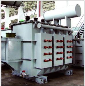
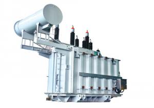
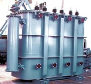
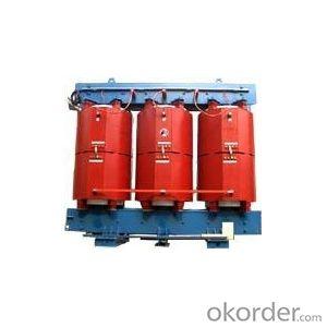
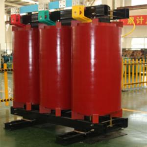
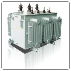
Furnace transformer of HS9 HSZ9 HSP9 series
- Ref Price:
-

- Loading Port:
- China Main Port
- Payment Terms:
- TT OR LC
- Min Order Qty:
- -
- Supply Capability:
- -
OKorder Service Pledge
OKorder Financial Service
You Might Also Like


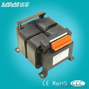

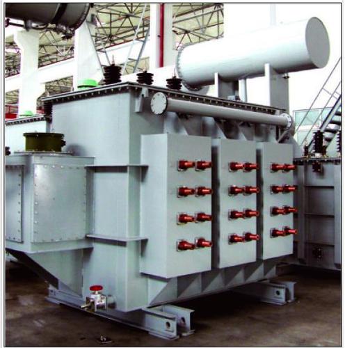
Furnace transformer of HS9,HSZ9,HSP9 series
1. Product introduction
The furnacetransformer is a transformer for power supply to furnace electricalsource. It is used to reducea voltage from a high voltage to an operational voltage needed by furnace.
Accordingto many different types of furnaces,there are many varieties of furnace transformer to fit it.At present, the furnace transformers produced by ourcompany are: electric arc furnace transformerused for steel-making furnace (including on-load and no-loadhigh voltage and enclosing reactortype); the furnace transformers (single - -phase, three-phase on-load and no-load voltage regulating) usedfor smelting various ferroalloy, silicon compounds, mineralssuch as calcium carbide, are all the low-loss energy-saving products.
2. Technicalparameter
Furnacetransformer of HS9 HSZ9 HSP9 series
Rated Capacity (kVA) | With series reactor | Without series reactor | ||||||||||||
Primary voltage (kV) | Second voltage (kV) | Rated second current (A) | Voltage regulation mode | Label of connection | Impedance of short-circuit (%) | Series reactor | No-load loss(Kw) | load loss(Kw) | No-load current(%) | No-load loss (Kw) | Load loss (Kw) | No-load current(%) | ||
Rated Capacity (kVA) | Reactance voltage drop (%) | |||||||||||||
630 800 1000 | 6 6.3 10 10.5 11 | 200 1700 116 98 | 1819 2309 2887 | No load voltage regulating | Dd0 Dy11 | 8-9 | 120 150 190 | 19 | 2.4 2.7 3.1 | 8.6 11 14 | 3.0 2.9 2.9 | 2.2 2.7 3.1 |
11.0 13.5 16.0
| 3.0 2.9 2.8 |
1250 1600 2000 | 210 180 121 104 | 3437 4399 5499 | 200 260 320 | 16 | 3.6 4.1 4.6 | 17.5 22 27 | 2.6 2.5 2.4 | 3.7 4.6 5.6 | 18.5 24 28 | 2.6 2.5 2.4 | ||||
2500 3150 | 220 190 127 110 | 6561 8267 | 280 350 | 11.2 | 5.2 6.0 | 32 39 | 2.3 2.2 | 6.7 8.0 | 34.5 41.5 | 2.3 2.2 | ||||
4000 5000 | 240 210 139 121 | 9623 12028 | 340 360 | 8.5 | 7.6 8.4 | 46 54 | 2.1 2.0 |
|
|
| ||||
6300 8000 | 260 240 210 139 | 13990 17765 | 7-8 | 430 460 | 5.7 | 11.8 15.0 | 63 74 | 1.9 1.8 |
|
|
| |||
HSZ9 series 35kV on-load voltage regulatingelectric-arc-furnace transformer technical parameter
Type | Primary voltage (kV) | Secondary voltage | Secondary level voltage (V) | Rated secondary current (A) | Voltage regulating levels | Label of connection (%) | impedance of short-circuit (%) | Cooling | No-load loss (Kw) | Load loss (Kw) | No-load current(%) | |
Constant power | Constant current | |||||||||||
10000 | 35 38.5 | 280-240 | 240-100 | 10 | 24056 | 19 levels, first 5 levels are constant power output and last 14 levels are constant current output | Dd0 Yd11 YNd11 | 7-8 | OFWF or OFAF | 20 | 130 | 1.4 |
12500 | 314-270 | 270-116 | 11 | 26729 | 23 | 150 | 1.3 | |||||
16000 | 353-35 | 305-157 | 12 | 30287 | 28 | 180 | 1.1 | |||||
20000 | 392-340 | 340-158 | 13 | 33962 | 6-7 | 32 | 210 | 1.0 | ||||
25000 | 436-380 | 380-184 | 14 | 27984 | 39 | 240 | 0.9 | |||||
31500 | 489-425 | 425-201 | 16 | 42792 | 45 | 290 | 0.8 | |||||
40000 | 547-475 | 485-223 | 18 | 4819 | 52 | 350 | 0.7 | |||||
50000 | 610-530 | 350-250 | 20 | 54467 | 61 | 410 | 0.7 | |||||
63000 | 673-585 | 585-288 | 22 | 62176 | 68 | 480 | 0.6 | |||||
80000 | 760-660 | 660-310 | 25 | 69982 | 80 | 580 | 0.6 | |||||
- Q: i think transformers
- The simpsons by far! Transformers had too many effects,it got old after a while.
- Q: Transformer oil filter method
- Transformers in the run after a period of time, if due to short circuit and other causes of transformer oil quality electrical test failed to test the need for oil treatment, improve its purity. The main reason for failure is excessive water content, including other impurities. Transformers because it has been oiled and can not be all out of all the oil out of the filter processing.
- Q: How many transformers games are for the xbox360 and what ones are based on the old tv show? And what ones are based on the movies? Please give complete names and in order! Thank you (:
- Movie: Transformers: The Game (2007) Transformers: Revenge of the Fallen (2009) Transformers: Dark of the Moon (2011) Non-Movie: Transformers: War for Cybertron (2010)
- Q: Transformer total circuit breaker rated current 380v, rated current 1000a, the rated capacity and output power how to calculate, I did not learn more points
- Kva is the unit of apparent power, KW is the unit of active power. Apparent power equal to the root number (active square square + reactive power square)
- Q: If you're a transformers fan, who do you think were top 10 strongest Autobots in the whole transformers universe? I mean strongest of the strongest, most brutal and powerful?lol.
- TFC transformers cybertron 1: Primus (if he counts as an autobot) 2: vector prime (in his prime/glory days) 3: TFC metroplex 4: TFC quickmix 5: TFC optimus prime 6: TFC jetfire 5: TFC wingsaber 6: TFC landmine 7: TFC red alert (reborn) 8: TFC scattershot (reborn) 9: TFC hot shot (reborn) 10: TFC leobraker TFC totally dominates this list since they are the only version of transformers that can annihallate galaxies.
- Q: I live in Market Weighton and I need to know why my local electricity transformer is. Where will I need to look?
- For residential, the step down transformer for home electricity use is typically a pole top mounted transformer. It may be at the top of a power pole near your residence. Sometimes there may be a pad mount transformer (square metal box) near your home that is used. You may want to look outside your home, and see where the wires coming into your electrical service are coming from. That should tell you where the transformer is. If you live in a newer neighborhood, you may have underground service ( thus no power poles) and the transformer may not be visible. It would likely be close by in an underground electrical vault. There is a picture of a pole top transformer in the attached article below:
- Q: I have a few power tools, none of which are natively wired for 110-240v. In particular, a portable table saw, a router, and a mitre saw, all at 220v. Since the resale value of them are so low on auction sites, I was thinking of taking them with me when I shift home to the states. Would it be safe using those tools, for extended periods, whilst running them on a transformer?
- You can do that. Just make sure the transformer is rated for the power they will draw. Keep this in mind: American homes are wired with 220 volts. Only, they split the voltage into two 110 volt legs. Each leg to ground (or neutral) is 110 volts (also commonly referred to as 120 volts). But from one leg to the other is where you get the 220 (or 240) volts. My garage is wired with two legs of 110, which means I have 220 out there. I also have an outlet for 220 volts. Because some of the power tools I run demand more current, and run them simultaneously, the standard 110 outlets struggle to meet the demand. So what I did was to take a dryer cord and wire it into a pony panel where I can draw 110 volts from one leg to ground to power a table saw while the other leg powers the dust collection system. To try and run both those pieces of equipment on a single 110 line means a trip to the breaker to reset it because each draws enough power that when used together they draw more current than the circuit is safely rated for. YOU can do something similar. Just make sure you use a 20 amp outlet meant for use with 220 volts and wire into the panel (if not already wired) and set up a 220 volt plug where you will be using these power tools. Using a transformer will work, but the more you couple the power magnetically the more inefficient your system becomes, and you waste power. Also consider just buying tools rated at 110 volts. They're plentiful and cheap enough that the cost may offset the cost of shipping these 220 v tools. Throw in the cost of a transformer and you're probably spending more money in the long run. Hope this helps. '')
- Q: I am building a simple circuit and was wondering what is the difference between a coil and a transformer? Also, in my circuit I have a generator. My generator is made up of a coil and magnets. I would like to know do the amount of turns my coil is determine the power of the generator? When I select the gage wire I am going to use we that determine the amount of volts and current I can gain from my generator?
- A transformer is used to transfer power and either step up or step down the voltages. Hence for this purpose, the mutual inductance must be very high. The leakage inductance needs to be minimum. Thats why iron core is used. A Coil is a conductor generally wrapped in a helicoidal form by certain number of turns.
- Q: A step up transformer increases 17.7v to 120v. what is the ratio of the current in the secondary compared to primary? Assume 92% efficiency.HELP PLEASE
- Preliminary necessary comments. (i) This question - and consequently my answer - assumes that we have a perfect transformer: such a transformer will have an efficiency of 100 %. (If this was not a perfect transformer, then a great deal more data about the transformer would need to be supplied: it isn't). Hence, because the efficiency of the transformer in this question is less than 100%, that must be because a secondary current is flowing in the load, the details of which we do not know - or indeed need to know. (ii) Transformers are rated in terms of their product of volts and amps: called VA. They are NOT rated in terms of watts, since the manufacturer cannot assume that the load on the transformer secondary will have a unity power factor. (iii) When a transformer supplies current to a load, its on-load efficiency is the ratio of (VA)out to (VA)in. (VA)in primary VA; (VA)out secondary VA. Solution. Let the primary current Ip; let the secondary current Is. Let the primary voltage Vp; let the secondary voltage Vs. Let the efficiency n. Then we have: (VA)in Ip X Vp Ip X 17.7 (VA)out Is X Vs Is X 120. (VA)out n X (VA)in. so: Is X 120 0.92 X Ip X 17.7 i.e.: Is/Ip (0.92 X 17.7)/120 0.138/1 ? Hence, the secondary current is 0.138 that of the primary current. HTH, Skywave.
- Q: actually I've many questions :) I've opened many mobile chargers and I didn't found the usual (bulky) transformer . I found only a small transformer and I think it called smps transformer.1- I can't understand how bulky transformers can be replaced by small ones! what is the idea ?2- are smps transformers connected directly to 220 volt like the bulky transformers ? if no, what is the design of the circuit that makes small transformers are able to be connected to 220 volt ?3- do smps transformers make a voltage drop like the bulky transformers ? or they have another job ?4- some smps transformers have 4 pins and the other have 5 or 6 pins, I know it should have 2 pins for input and 2 pins for output, why some of therm have more than 4 pins ?Thanks in advance, I hope i'm not bothering you because of my many questions :)
- This was an electronic switching power supply that was no more need the 50c/s big and large transformer. The small transformer is a high frequency transformer that working on about 30Kc. Mostly it also has a step down winding output about 12V at 30kc. Do not hook 220V 50c/s to it !
Send your message to us
Furnace transformer of HS9 HSZ9 HSP9 series
- Ref Price:
-
- Loading Port:
- China Main Port
- Payment Terms:
- TT OR LC
- Min Order Qty:
- -
- Supply Capability:
- -
OKorder Service Pledge
OKorder Financial Service
Similar products
Hot products


Hot Searches
Related keywords

