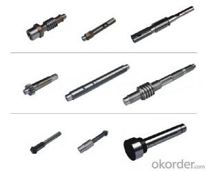

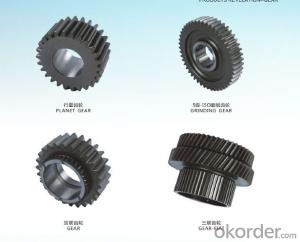
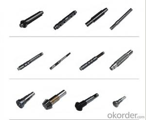
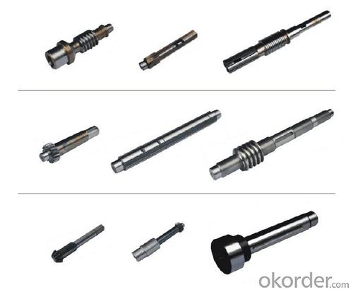
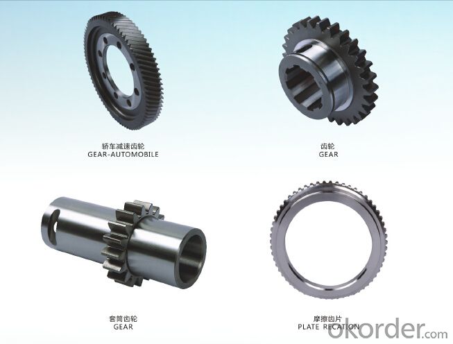


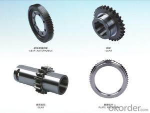
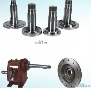
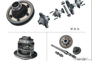
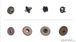
Forging and Machining Gear,Surfacetreatment
- Ref Price:
-

- Loading Port:
- Qingdao
- Payment Terms:
- TT OR LC
- Min Order Qty:
- 100 PCS
- Supply Capability:
- 5500 PCS/month
OKorder Service Pledge
OKorder Financial Service
You Might Also Like
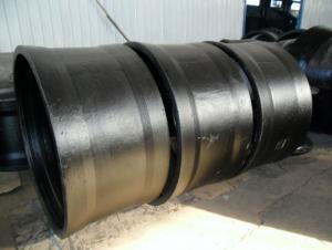
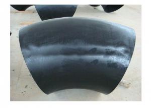
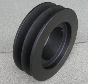
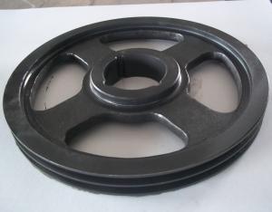
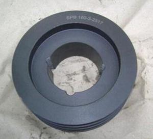
Item: Forging and Machining Gear,Surfacetreatment
Name:Gear
Detail:
Production Process: model forging and machining
Standard: ASTM, AISI, DIN, BS and JIS
Gear Forging Size: 1 meter
Gear Forging Weight: 0.2~80Kg
Gear Dimension Tolerance: CT7
Gear Surface Roughness: Ra6.4~12.5
Gear Productivity: 7500 tons per year
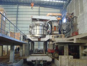
A world class manufacturer & supplier of forging in carbon steel and alloy steel, is one of the large-scale professional investment forging production bases in China, consisting of both casting foundry forging and machining factory. Annually more than 13000 tons Precision casting and forging parts are exported to markets in Europe,America and Japan. OEM casting and forging service available according to customers requirements..
- Q: Can the data be taken at will as required?
- At least greater than 2; size 2 is the same as above; size 3 (diameter) shall meet the diameter of the axial part of the bevel gear; do not interfere
- Q: Single tooth bevel gear box bearings generally choose what type, I do not have wealth value, please forgive me
- General use of such bearings, cone roller bearings, if the speed is very fast, automatic self-aligning bearing is also OK
- Q: Why does the bevel gear reducer put the cone gear at the high speed stage?
- When the driving power is constant, the torque of the high speed stage (shaft) is small, and the torque of the low speed stage (shaft) is large
- Q: What are the differences between the conical cylindrical gear reducer and the cylindrical bevel gear reducer?
- Form 90 degree direction output of screw conveyor. Instead of the real cone gear reducer.
- Q: How do we calculate the cone angle of straight bevel gears?
- 2, when the angle is less than 90 degrees (i.e. two into acute angle)Sub cone angle Delta 1=arctan[sin sigma / (U+cos sigma)]
- Q: The main function of gear drive is
- The utility model is characterized in that the utility model can be used between two shafts, not parallel, and can be driven at a certain angle (usually vertical).
- Q: What are the machining methods of bevel gears?
- Specializing in the design and production of high-end precision gear rack, worm gear, spiral bevel gear, straight bevel gear, spiral arc bevel gear, gear grinding processing, worm reducer, gear box of professional manufacturers.Products are widely used in China's automotive, machine tools, power, metallurgy, mining, engineering, lifting transport, ships, locomotives, agricultural machinery, light industry, construction and military industry and other fields.
- Q: What kind of straight bevel gear is suitable for processing? Thank you
- In general, the preferred gear shaper, suitable for small batch, multi variety, easy conversion products. Large batch of cases, using Y2725E double disc milling machine, efficient, but difficult to adjust the machine.
- Q: As the two bevel gear graph, the original assembly is the shaft angle of 90 degrees, and now I want to change my point of view, do not know what way. The pin connection is used to try to build another axis that is not vertical, but the rotation option is missing. Is there any way to solve it?. PS: I'm a newbie at Proe, and I don't know much about the options. Please try to be more specific
- Want to change the angle?:Redefine your shaft angle in the assembly mode (80 degrees)Modify your bevel gear pair so that it meets assembly Sigma =80 (refer to the mechanical design manual to change the parameters of the two gears)The rest don't need to be changed, and you don't have to redraw it. The PROE parameterized design is that you can get the model you want just by changing the parameters.Try it yourself, but don't ask again.
- Q: The big end of the bevel gear to which part?
- Bevel gear commonly two contraction form, one is tooth thickness contraction, one is double contraction, double contraction most. As the name suggests is the ends of bevel gears of different thickness, different tooth height, the small end of a mean cone diameter and small diameter at both ends, at the same time, the teeth at both ends are of different sizes, large diameter of a tooth is also big, big, and small end
Send your message to us
Forging and Machining Gear,Surfacetreatment
- Ref Price:
-
- Loading Port:
- Qingdao
- Payment Terms:
- TT OR LC
- Min Order Qty:
- 100 PCS
- Supply Capability:
- 5500 PCS/month
OKorder Service Pledge
OKorder Financial Service
Similar products

Hot Searches
Related keywords

