
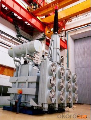
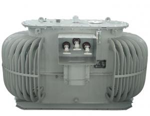
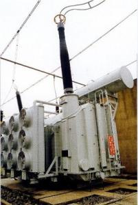
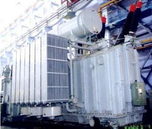
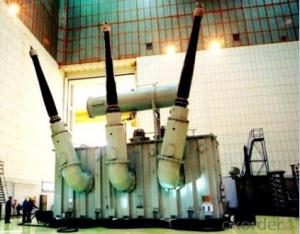
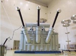
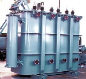
250MVA/500kV main transformer power station phase
- Ref Price:
-

- Loading Port:
- Tianjin
- Payment Terms:
- TT OR LC
- Min Order Qty:
- 1 pc
- Supply Capability:
- 1 pc/month
OKorder Service Pledge
OKorder Financial Service
You Might Also Like


Quick Details
| Place of Origin: | HeBei | Brand Name: | CNBM | Model Number: |
|
| Usage: | Power | Phase: | Three | Coil Structure: | Toroidal |
| Coil Number: | 3 Winding | Capacity: | 50000 63000 80000 100000 120000 180000 | Rated Voltage: | 250MVA/500kV |
| Connection Symbol: | YNd11 Dyn11 YNyn0d11 | Tank: | Cover type or Bell type | OLTC: | MR or ABB or SMS |
Packaging & Delivery
| Packaging Detail: | Mainbody --naked Disassembled parts -- crate |
| Delivery Detail: | 3 months |
Specifications
1. CESI certificate
2. High short-circuit withstand
3. Low loss, PD and noise
4. CTQC certificate
5. No leakage
Description
The application of 250MVA/500kV main transformer power station phasecan significantly improve the economy of the UHV substation, and matches well with the transmission capacity of UHV lines, which has wide prospect of application. Because of its large capacity and large volume, the whole transportation weight with nitrogen is about 470-490 tons, and due to the restricted transport conditions, the transportation becomes the critical issue for application of the 250MVA/500kV main transformer power station phase. In order to make the products applicable to any UHV substation in our country, the state grid of corporation of China set the "A study of easy-transport large capacity UHV Transformer” as a key scientific research projects, and entrusted BTW to carry out the research.
During the process of research and development, BTW adopted the advanced design technology and modular design, the transformer can be transported disassembly and with advantages of compact core and winding body, less transportation weight and low transportation cost, effectively solves the need of UHV construction in the transportation restricted areas. By using the most advanced 3D magnetic field calculation software, BTW performed detailed analysis and calculation for the magnetic flux leakage and eddy current loss of the transformer coil, iron core and oil tank steel structures. Besides, by using of the advanced electric field calculation software, BTW performed detailed analysis and calculation of main longitudinal insulation, and mastered the arrangement of the main longitudinal insulation of large capacity UHV transformer and the control of distribution of winding magnetic flux leakage. All of which make the products with low loss, low noise, small volume, strong anti short circuit ability, no local overheating and other significant advantages, and guarantee the long-term safe and stable operation.
The world's first on-site assembled large capacity UHV Transformer’s right at the first time once again filled the gap in the field of UHV transformer research after Chinese transformer industry overcame the difficulty of integral transport of 250MVA/500kV main transformer power station phase, which marks BTW has fully occupied the world transformer industry technical peak. The successful development of the product filled the gaps in the domestic technology and met the urgent need of UHV construction application in our country, greatly improved the technical level and manufacturing ability of BTW in terms of UHV Transformer products.
- Q: I have a DC current transformer and it is a 2500:1. I do not know what this means but I have a rectifier hooked up to it and am measuring the output DC voltage. I have hooked up resistors in values of 20Ω, 2kΩ, 10kΩ, and 20kΩ. I do not know how to convert to amperes though the resulting DC volts. How can this be done?
- NO such thing as a DC transformer. Do you mean an AC voltage transformer with rectifiers on the output? But ohms law should apply. Current voltage divided by resistance.
- Q: I'm building a ark welder and i know they get very hot, iv seen some people in ''the internet'' submerging their transformers in transmission fluid to keep em cool under excessively heavy work loads.My question is what effects does oil have on wire insulation?And what about the transformer varnish and core insulation wads and paper?
- Only impurities will have an effect on insulation. Best if boiled first to remove any condensation, then seal the container.
- Q: can anyone pls explain to me about electronics .I mean in simple words to let me know,what does a transformer an i.c. and all that we see on an electronic board ??
- TRANSFORMER: transformer is a device that transfers electrical energy from one circuit to another through inductively coupled electrical conductors. A changing current in the first circuit (the primary) creates a changing magnetic field; in turn, this magnetic field induces a changing voltage in the second circuit (the secondary). By adding a load to the secondary circuit, one can make current flow in the transformer, thus transferring energy from one circuit to the other. for details:
- Q: Distribution transformer
- The low voltage winding is placed closer to the core because the high voltage winding requires more space due to its MV insulation. If designers put the LV winding outside the MV winding, the tank would be larger because the _MV_ winding size would be about the same size. More insulating oil would be required, and the leakage reactance would be significantly higher. Remember, higher leakage reactance means that the voltage regulation (more aptly voltage drop) under load will be higher, which is not desirable. And, of course, a larger tank and more oil make for a more expensive transformer. Edit: MV winding is about the same size for either configuration, due mainly to insulation requirements.
- Q: I want to step down a 240Vpeak signal to 24. Anyone know where I can get a transformer to do this? Also does frequency have a dependence on a transformer? The signal I am looking at has around 55Khz frequency. Thanks for your help
- You won't be able to find a transformer for that frequency, unless you are lucky. You will have to wind your own. Probably a ferrite core is best, depending on your power level, which you did not mention, and is an important design factor. If this is a very low power signal (you do use the word signal), perhaps a capacitive or resistive voltage divider will be enough. Or search for an audio signal transformer. .
- Q: Step-up transformer, low-voltage winding put the middle, that is, low-high; Step-down transformer, medium voltage winding in the middle, that is, low high. For the step-up transformer, the input is low and the output is high or medium; the low-lying intermediate makes it possible to minimize the distance in the low-high, low-, thereby reducing the distance traveled by the magnetic energy, Loss, reduced low - high, low - in the leakage resistance, thereby reducing the low - high, low - between the short - circuit voltage percentage, thereby reducing the reactance, thereby improving the energy conversion efficiency of the transformer. For buck transformer, the input is high, the output is low or medium, similar to the step-up transformer, the optimal arrangement should be low, high, medium. However, due to insulation safety problems, the high voltage side must be placed at the outermost end. So the arrangement of sub-optimal way to low, medium and high.
- 2, from the manufacturing cost considerations, the transformer core is grounded. Low voltage coil inside, the coil on the core of the insulation distance can be smaller. So that the sum of the main insulation dimensions of the three coils will be smaller. The weight of the entire transformer, the volume is relatively lower than the - low - high arrangement to be smaller.
- Q: A stepdown transformer is used for recharging the batteries of portable devices such as tape players. the turns ratio inside the transformer is 13:1 and it is used with 120 V rms household service. if a particular ideal transformer draws 0.350 A from the house outlet, what are the voltage and the current supplied to a tape player from the transformer. How much power is delivered?
- Tape Player Transformer
- Q: Transformer three-phase imbalance which harm
- 1, when the line is not full-phase operation, the zero sequence current is equivalent to the load current, then the line with its adjacent line zero sequence current may be large, even greater than the zero sequence backup protection settings, if not quickly cut Non-full-phase operation of the line, it may lead to adjacent line malfunction, leap-off; 2, for 220kV and above generator transformer group and machine-side circuit breaker, due to non-full phase operation during a larger negative sequence current, the generator, the transformer may cause a greater damage to the equipment.
- Q: Is the transformer a power adapter?
- No, the transformer should be a device that performs impedance matching in order to achieve maximum power transmission. In turn, "power adapter is a transformer" is also unsatisfactory, at least the general power adapter contains a transformer. As a power adapter requires a common power supply into a device required power, voltage, current, impedance and other aspects of the match, of course, it needs a transformer. Since it has the function of changing the voltage, call it "transformer" is no harm. I would like to say that the power adapter is not only transformer, it needs to achieve in addition to the voltage other than the parameters of the match, for example, the most simple general-purpose DC adapter in addition to transformer that there is a "rectification" process. The transformer, narrow sense that it is just a component only, like resistors, capacitors, transistors and so on.
- Q: Photovoltaic grid-connected system, with the inverter with the role of transformer. In the choice of inverter with a transformer and without a transformer, how should choose? That is the isolation, I do not quite understand. Who knows that high! Thank you!
- Inverter with a transformer is played a role in isolation, it can provide you with pure sine wave current, so that the PV grid-connected system can provide a more secure and reliable isolation.
Send your message to us
250MVA/500kV main transformer power station phase
- Ref Price:
-
- Loading Port:
- Tianjin
- Payment Terms:
- TT OR LC
- Min Order Qty:
- 1 pc
- Supply Capability:
- 1 pc/month
OKorder Service Pledge
OKorder Financial Service
Similar products
Hot products


Hot Searches
Related keywords

