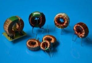
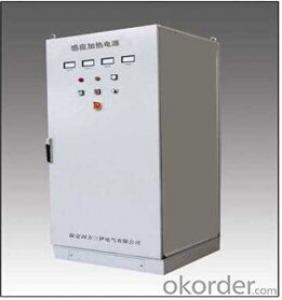
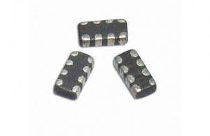
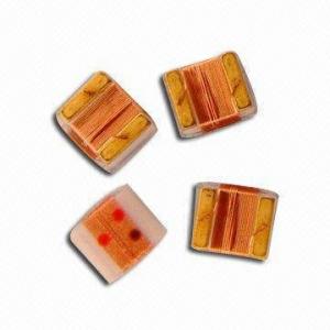
Low Frequency Toroidal Needle Insert PCB Mounted Transformer
- Ref Price:
-

- Loading Port:
- China Main Port
- Payment Terms:
- TT or LC
- Min Order Qty:
- 1000 Pieces pc
- Supply Capability:
- 30000 Pieces per Month pc/month
OKorder Service Pledge
OKorder Financial Service
You Might Also Like
1.Professional engineer
2.Qualified material competative price
3.small loss
4.usage:power phase:single coil
5.structure:toroidal
6.core dimension:adjustable by clients
7.size:follow customer's request
8.Remark:we can produce it according client's requirement
Our products have gained the international certifications, such as CQC, CE, RoHS, UL and so on, from internationally powerful authorities. We have got ISO9001 certificate.We promise to offer the best products to our clients.We look forward to cooperating with all friends for more mutual benefits.
- Q:I always wandered about that.
- Mathematically you would have to be familiar with complex numbers and some calculus. that is why Thomas Edision used DC and N. Tesla and Westinghouse used AC. by analogy. It is like the mass and spring. inertia keeps the mass moving, the spring tries to return it to center but the inertia makes it overshoot in the other direction and you get oscillations., electrically the inductor is an inertia like effect and the capacitor is a spring like effect. It took me a long time to understand this. In the 1850's James Clark Maxwell wrote and solved vector calculus differential equations for all the known electrial effects and prediticted electro-Magnetic waves in space that had exactly the velocity of light, showing that light and radio were all the same thing. that was before radio was invented. How is that for Nerds Rule
- Q:1.) A pure capacitor, a pure inductor and a pure resistor are connected in series across an ac power source. A voltmeter placed in turn across each circuit element reads 15V, 20V, and 20 V, respectively. What is the potential difference of the source?2.) A 50-uF capacitor is connected in series with a 300-ohms resistor, and a 120-V, 50-Hz potential difference is applied. Find the current in the circuit and the power dissipated.
- 1) 20.6V 2)0.276 amps 33 watts
- Q:Can the current in an inductor change instantaneously?
- It would require a theoretically infinite voltage to do this. V L di/dt
- Q:help me to know the basics of tapping an inductor
- For small air-core inductors there are a couple of methods that I have used. 1. Wind 10 turns and carry the end lead out about 1 inch away from the coil, then carry the wire back next to the 1 inch lead, back to the coil and continue winding for another 30 turns. Scrape off the insulation of the double-wire lead and use that as the tap. 2. Wind 10 turns. Scrape off the insulation at the 10th turn, leaving an opening to solder a wire on the coil. Continue winding 40 turns. Solder a wire onto the scraped off opening for use as the tap. I like the first method best, but both will work. .
- Q:For AC Power, Real Power (P) formula is PVrms^2/R.With that said, does that mean that if I connect an ideal inductor to 120V @60 Hz, I will have infinite Real Power?, because an ideal inductors resistance (R) is 0. So, Real Power 120/0 Infinity.That means I will use an infinite amount of energy if I connect the inductor to the power line.
- I try not to feel too much. It leads to crazy, irrational decisions. And if I do feel an overwhelming wave of intense emotion, I assume it is caused by hormones. You might think I'm being rude and sarcastic, but I promise I'm being honest here.
- Q:I want to check and see if I understand all of this correctly, so I'll list what I am thinking happens and you can correct me if I'm wrong, Ok?I am talking about a very basic inductor in a very basic DC circuit, I am only wanting to understand the operation of an inductor in a circuit.1. When the cirucit is first energized the coil acts like a resistor, it drops the maximum amount of voltage ( the amount of the source) which declines rapidly as the field builds. The voltage it drops is opposite to the increase in polarity only, equal in value.So it is exhibiting decreasing resistance to current flow in this charging state.2 As current is decreased, the coil releases its energy by dropping a voltage of the same polarity to attempt and maintain the current's prior state. It is acting as a source in this state, but increasing its resistance to the change as its field deteriorates. 3. Steady state of current.NOT Sure?
- in transient the coil acts like a short circuit ( the resistance is omitted ) after the transient it acts like a currenr source that oppisite the true current when the field collspse it will be just like a short circuit or a very small resistance you must be very carful for example never plug a transformer - AC adapter for example - in DC voltage cuase it will be just like short circuiting the DC source and this dangerous as for what you ask you will only need it if you study transient circuit behavior for steady state in DC circuit you can treat the inductor as a short circuit or a very small resistance NOTE:the inductor behaveor very differnt in AC circuir
- Q:A current of 1.24A in an inductor L results in a stored energy of 0.195J. The current is then changed to 6.47A in the opposite direction. Calculate the change of stored energy.
- Situation 1: MPE1 1/2*L*I1^2 Situation 2: MPE2 1/2*L*I2^2 L doesn't change, since it only depends on geometry and core material properties of the inductor. Solve for L in situation 1: L 2*MPE1/I1^2 Substitute: MPE2 MPE1 * I2^2/I1^2 We are interested in MPE2 - MPE1: MPE2 - MPE1 MPE1*(I2^2/I1^2 - 1) Data: MPE1:0.195 J; I1:1.24 A; I2:6.47 A; Result: MPE2 - MPE1 5.1138 Joules
- Q:A certain solenoidal inductor has a magnetic flux of 835 μWb through each loop of its coil when the current flowing through it equals 0.600 A. If the solenoid has 125 loops, what is its inductance (H)?
- Magnetic flux Φ is calculated by Magnetic Circuits Ohms Law Φ F_M/R_M N I /R_M where Φ is magnetic flux in Webers (Wb). F_M is magneto-motive force in Ampere-Turns (A?T). F_M N I N is number of turns on solenoid in turns (T). I is current in solenoid in Amps (A) R_M is reluctance in A?T/Wb. Solve for reluctance. R_M N I /Φ 125 turns * 0.600 A/ 835 μWb 75A?T/ 835 μWb 89820 A?T/Wb Inductance L N^2/R_M (125 turns)^2/89820 A?T/Wb 0.174H
- Q:I know this is a very broad question, but what would be a decent ball park estimate for resistance (in ohms) in an inductor that would be found in a parts bin at a university. The inductors values range from 2mH to 100mH. But, more specifically, is it over or under 300 ohms?
- It will probably be less than 300 ohms. Varies, but it's just a length of copper wire, it can be as low as less than an ohm. That is a very narrow range of inductors, usual values are in the 10 - 1000 ?H. edit: A little research turns up an audio inductor of 100mH that has 1000 ohms DC resistance, so higher resistance is possible. .
- Q:A 1.15 kilo Ohms resistor and a 590 mH inductor are connected in series to a 1350 Hz generator with an rms voltage of 12.1 V.What is the rms current in the circuit in mA?What capacitance must be inserted in series with the resistor and inductor to reduce the rms current to half the value found in part A in nF?
- A) the reactance of the inductor is XL 2π*f*L 2π*1350*0.590 5005Ω So the impedance Z sqrt(1150^2 + 5005^2) 5135Ω Therefore the rms current V/Z 12.1V/5135Ω 2.36x10^-3A 2.36 mA B) If the current is reduced to 1/2 then then impedance must double So Z sqrt(R^2 + (XlL- XC)^2) 10270 So 1150^2 + (5005 - XC)^2 10270^2 or 5005 - XC +-sqrt(10270^2 - 1150^2) +-10205 or XC 5005 + 10205 15210 Now XC 1/2πf*C or C 1/(2π*1350*15210) 7.75x10^-9F 7.75nF
1. Manufacturer Overview |
|
|---|---|
| Location | Shenzhen, Guangdong, China (Mainland) |
| Year Established | 2006 |
| Annual Output Value | US$2.5 Million - US$5 Million |
| Main Markets | North America; South America; Eastern Europe; Southeast Asia; Africa; Oceania; Mid East; Eastern Asia; Western Europe; Central America; Northern Europe; Southern Europe; South Asia; Domestic Market |
| Company Certifications | CE Certificates |
2. Manufacturer Certificates |
|
|---|---|
| a) Certification Name | |
| Range | |
| Reference | |
| Validity Period | |
3. Manufacturer Capability |
|
|---|---|
| a)Trade Capacity | |
| Nearest Port | Shekou,Yantian |
| Export Percentage | 51% - 60% |
| No.of Employees in Trade Department | 3-5 People |
| Language Spoken: | English, Chinese |
| b)Factory Information | |
| Factory Size: | 3,000-5,000 square meters |
| No. of Production Lines | 9 |
| Contract Manufacturing | OEM Service Offered Design Service Offered Buyer Label Offered |
| Product Price Range | Average |
Send your message to us
Low Frequency Toroidal Needle Insert PCB Mounted Transformer
- Ref Price:
-
- Loading Port:
- China Main Port
- Payment Terms:
- TT or LC
- Min Order Qty:
- 1000 Pieces pc
- Supply Capability:
- 30000 Pieces per Month pc/month
OKorder Service Pledge
OKorder Financial Service
Similar products


New products


Hot products

Related keywords

