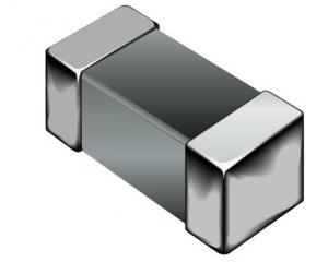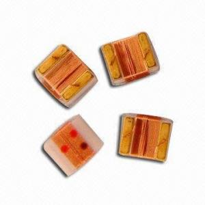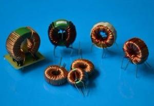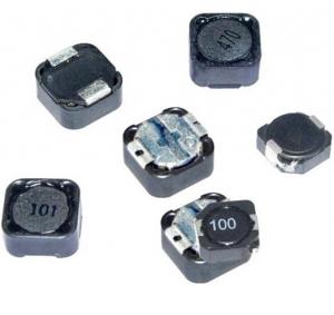
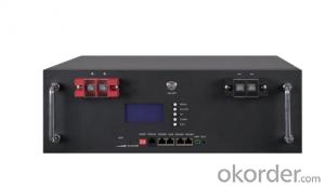
PBH/PBL SERIES SMD Power Inductor
- Ref Price:
-

- Loading Port:
- China Main Port
- Payment Terms:
- TT or LC
- Min Order Qty:
- 3000 Pieces pc
- Supply Capability:
- 20,000 Pieces per Day pc/month
OKorder Service Pledge
Quality Product, Order Online Tracking, Timely Delivery
OKorder Financial Service
Credit Rating, Credit Services, Credit Purchasing
You Might Also Like
Features:
1.SMD Power Inductor
2.Magnetic shieled surface mount inductor with high current rabing low D.C resistance
3.Excellent terminal strength
4.Packed in embossed carrier tape and can beused by automatic mounting machine.
5.Various hogh power inductors are superior to be high saturation for suiface mounting
Applications:
Power supplu for VTR,OA equipment Digital camera, LCD television set notebook PC, portable
communication equip,ents, DC/DC converters, etc.
- Q:Does current flow through an inductor if it is connected to a dc source without any other component such as resistance or capacitor?
- In a real situation, yes. Though this would be a brief and violent flow (since you're assuming the resistance is negligible). In an ideal circuit analysis, such a circuit is impossible, meaning that the circuit equations produce an undefined result. For example, the voltage across an inductor is: V L*?i/?t. Since the current does not change for a DC source, the result is V 0. This is well and good provided that your source is outputting zero volts. If not, you have a disagreement in your system of equations. This is assuming, of course, that your ideal situation does not include transients. If you have no resistance, though, the calculation of transients would be problematic as well (though not impossible.)
- Q:I can't quite seem to understand how to solve this set of problems:A 12.0 V dc battery having no appreciable internal resistance, a 150 Omega resistor, an 11.0 mH inductor, and an open switch are all connected in series. 1.)After the switch is closed, what is the time constant for this circuit ?2.)After the switch is closed, what is the maximum current that flows through it ?3.)What is the current 73.3 microsecond after the switch is closed ?4.)After the switch is closed, what is the maximum energy stored in the inductor?------I got the answer to number one.but i don't understand why its 73.3 microsecond rather than 7.33 micro second. And i can't get the right answers for the rest of the questions even though I've tried using all the equations.
- 1) time constant T L/R T 11*10^-3/150 T 7.33*10^-5 s T 73.3*10^-6 s T 73.3 us 2) After a long time the inductor will appear to be a short circuit, and the maximum current is I V/R I 12/150 I 0.08 A 3) i Io*(1 - e-t/T) i 0.08*(1 - e-73.3/73.3) i 0.05 A 4) W L*I^2/2 W 11*10^-3*(0.08)^2/2 W 0.0000352 J
- Q:Having a bit of trouble with this question; I'm asked to calculate the time in ms it takes to dissipate 40% of the initial stored energy of an Inductor.I know that the initial stored energy is 62.5 JThe time constant is 50msV 200e^(-20t)I 12.5e^(-20t)I've worted out the above values, but I cannot see how I can work out the time taken for it to discharge 40%, as i keep getting a negative time value.I would be very grateful of any help :)(P.S. I also need the same for a capacitor when I have similar values)
- 0.4 e^(-20t) ln(0.4) -20t t ln(0.4)/(-20) t (-0.916)/(-20) t 0.0458 46ms
- Q:How does the inductor and tuning capacitor together work in the AM Radio Reciever?How does it pick up the frequency I want? What is the principle behind it?
- Basically the inductor is a coil. When connected to a battery or some other power source in parallel it discharges, or shorts. On the other hand a capacitor stores electricity. In a tuning circuit, these two are connected parallel. So you can imagine the outcome. when power is supplied, capacitor stores the electricity while the stored electricity quickly gets discharged via the inductor. again the same process. This process happens again and again and the outcome is a signal of a fixed frequency. This frequency depends on the capacitor value and the inductance. So the frequency can be varied when one or both of these are varied. Thats where the tuning capacitor comes in. Hence now we can make a variable frequency. In the radio, the antena absorbs all signals from the space that it can absorb, so various frequencies are absorbed. We get a signal with all frequencies in it. Then a selected frequency is absorbed to a transistor. This selected frequency depends on the frequency I explained at first. After going through the transistor we get the desired radio frequency which we listen through the earphones. Hence by varieng the frequency I described first you get different chanels.
- Q:i want to know about the AC operation of capacitor and inductor that why leading and behind is accruing
- had the same problem but found i just hadnt turned the plug on at the wall
- Q:A 29.0 mH inductor has a reactance of 1.50 k.(a) What is the frequency of the ac current that passes through the inductor? 51000 (b) What is the capacitance of a capacitor that has the same reactance at this frequency? (c) The frequency is tripled, so that the reactances of the inductor and capacitor are no longer equal. What is the new reactance of the inductor? (d) What is the new reactance of the capacitor?
- a) The reactance of an inductor is given by X w L 2 pi f L thus the frequency is f X / 2 pi L 1500/(2*pi*29E-3) 8232 Hz b) The reactance of a capacitor is X 1 / 2 pi w C solving for C we get C 1 / (2*pi*X) 1 / (2*pi()*8232*1500) 1.28891E-08 F c) and d) use the expressions above to calculate the new reactances replacing w with 3*w.
- Q:An inductor in the form of a solenoid contains 400 turns, is 15.0 cm in length, and has a cross-sectional area of 3 cm2. What uniform rate of decrease of current through the inductor induces an emf of 175 ?V?
- EMF - dΦ/dt -μ?NA/L (di/dt) di/dt - (1.75x10^-4)(0.15) / (4π×10^-7)(400)(3x10^-4) - 174 Amp/sec
- Q:I have built a basic telegraph to test the inductor on my scope to verify what I have been taught. I wrapped my coil around a drill bit from bottom to top in a clockwise direction with the negative lead on the bottom, positive on top. I connect the battery positive directly to the top of the coil ( positive) and the negative battery to the key switch, from the switch to the lower end of my coil. I expected as the switch was closed and current was increasing that the coil will attempt to keep it the same ( zero) by reducing the voltage by an equal amount while it is building its magnetic field. However, I am seeing a positive spike rather than a negative and I do not know why. I have connected my scope negative to the bottom of the coil ( negative) and positive to the top of the coil ( positive). Like i said, I expected a negative spike in voltage, but i am seeing a positive spike which reduces to the positive battery voltage. Please Explain ?
- It is a bit difficult to visualize the experimental setup, but what I would expect that you see is this: when you close the key, the voltage across the coil should rise rapidly to the battery voltage, as the current increases, limited only by the coil and battery resistance. The scope will measure the sum of the voltage due to the coil inductance and the coil resistance, the voltage due to inductance will quickly deline to zero, and the voltage will approach the battery voltage asymptotically. Life gets much more interesting when you open the key: the current flowing through the inductor attempts to flow through the opening key contacts and will produce a spark, and you will see a large voltage spike on your oscilloscope. Figure out what the polarity should be, and see if that is what you get.
- Q:A constant voltage of 5.00 V has been observed over a certain time interval across a 1.10 H inductor. The current through the inductor, measured as 2.00 A at the beginning of the time interval, was observed to increase at a constant rate to a value of 6.00 A at the end of the time interval. How long was this time interval?
- Jag tycker det ?r lustigt hur du ska ?vers?tta detta f?r att se vad jag skrev. L?ser du fortfarande h?r? Du borde sluta nu.
- Q:A series circuit consists of a 0.45 H inductor with internalresistance 6.0 ohms connected in series with a 8.0 ohm resistor, aswitch, and a 12 volt battery. Twenty milliseconds after the switch isclosed, how much energy is stored by the inductor?I understand that energy 1/2LI^2 Lmagnetic flux/I energy1/2 (magnetic flux)*Iand that’s as far as I can get. Any help?
- your barking up the wrong tree trying to use magnetic flux. V Ldi/dt instantaneous V across the inductor 12*6/14 5.14 V/L di/dt 5.14/0.45 11.4 A/s Power 58.74W 58.74 J/s in 20ms, E 58.74*0.02 1.17J This answer makes a number of assumptions, including a constant voltage and assumes di/dt is linear which may not be true.
Our products have highest quality and competitive prices.Our well-equipped facilities and excellent quality control throughout all stages of production enable us to guarantee total customer satisfaction. As a result of our high quality products and outstanding customer service, we have gained a global sales network.
1. Manufacturer Overview |
|
|---|---|
| Location | Guangdong,China (Mainland) |
| Year Established | 2010 |
| Annual Output Value | US$10 Million - US$50 Million |
| Main Markets | North America; South America; Eastern Europe; Southeast Asia; Africa; Oceania; Mid East; Eastern Asia; Western Europe |
| Company Certifications | ISO 9001:2000 |
2. Manufacturer Certificates |
|
|---|---|
| a) Certification Name | |
| Range | |
| Reference | |
| Validity Period | |
3. Manufacturer Capability |
|
|---|---|
| a)Trade Capacity | |
| Nearest Port | |
| Export Percentage | 41% - 50% |
| No.of Employees in Trade Department | |
| Language Spoken: | |
| b)Factory Information | |
| Factory Size: | |
| No. of Production Lines | |
| Contract Manufacturing | OEM Service Offered Design Service Offered Buyer Label Offered |
| Product Price Range | |
Send your message to us
PBH/PBL SERIES SMD Power Inductor
- Ref Price:
-
- Loading Port:
- China Main Port
- Payment Terms:
- TT or LC
- Min Order Qty:
- 3000 Pieces pc
- Supply Capability:
- 20,000 Pieces per Day pc/month
OKorder Service Pledge
Quality Product, Order Online Tracking, Timely Delivery
OKorder Financial Service
Credit Rating, Credit Services, Credit Purchasing
Similar products


New products

Hot products