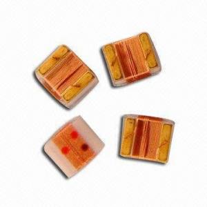
SMD Multilayer Ferrite Chip Bead
- Ref Price:
-

- Loading Port:
- China Main Port
- Payment Terms:
- TT or LC
- Min Order Qty:
- 4000 Pieces pc
- Supply Capability:
- 4000 Pieces per Day pc/month
OKorder Service Pledge
OKorder Financial Service
You Might Also Like
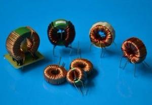
low frequency Inductor/filter
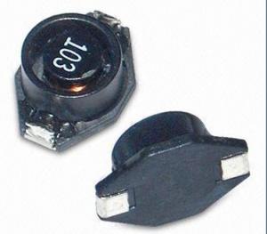
1.SMD multilayer ferrite chip bead
2.Low Crosstalk/DCR Features
3.competitive price
4.by customer's requests
Features:
1.Low crosstalk/DCR, high reliability
2.Low crosstalk between adjacent circuits
3.Single MZA series chip provides noise attenuation for four lines, ideal for various highly miniaturized I/D lines
4.Internal electrodes feature low DC resistance, minimizing wasteful power consumption
5.Electroplated terminal electrodes accommodate flow and reflow soldering
6.Monolithic structure ensures high reliability
7.Operating temperature range: from -25 to 85 degree Celsius
Applications:
1.High-frequency noise counter measured in computer
2.Printers
3.Portable telephones and other equipments
4.VCRs
5.Televisions
- Q:An inductor has a 54.0Ohms reactance at 60.0 Hz. What willbe the maximum current if this inductor is connected to a50.0-Hz source that produces a 100-V rms voltage?
- the impedance it given to you from the formula sq. root R^2+(XC-XL)^2 which could provide you 360.40 4 ohms for this reason Z multiplies via the amp of 233mA is 80 3.98V wish this helps
- Q:An engineer is asked to design a 10mH inductor. They design an inductor with the following parameters 500 turns of 30 AWG wire, the lengh of the coil i 1.9 cm and the diameter o the coil i 1 cm, and the core is ferrite with a permeability of 20 micro H/m. What i the actual impedance o the coil design?Also, which statement would most correctly describe how you would fix the design to the inductance of the inductor is 10mH? Why?A) Double the diameter of the coil to 2cmB) Halve the number o turns to 250C) Decrease the number o turns to 350D) Increase the number o turns to 650E) Halve the diameter of the coil to .5 cm
- ** C) Decrease the number of turns to 350. What is he actual INDUCTANCE, not impedence, which would only occur at a specific frequency, ok. Using the formula or calculator at source, gives inductance for values as 20.667mH. Now adjust design to yield 10 mH . Because the inductance is proportional to the square of the number of turns. So 500? 250000 Make this half 125,000 Get √125,000 353.55, Which is close enough to 350, Answer Check on calculator to confirm. Please request clarification, if required.
- Q:(leading/lagging)?
- First of all, remember that the question only has meaning if you are discussing an AC circuit being driven by a sine wave (not a square wave or any other waveshape) In a resistor, the current flowing through it is in phase with the voltage applied across it. In a capacitor, the current flowing through it is π/2 Radians (or 90°) ahead of the voltage applied across it. (This is also called 'leading' the voltage) In an inductor, the current flowing through it is π/2 Radians (or 90°) behind the voltage applied across it. (This is also called 'lagging' the voltage) In a resistive circuit, it is the resistance value which limits the current flow. In an inductive or capacitive circuit, it is a thing called the 'reactance' of the capacitor (capacitive reactance) or the inductor (inductive reactance). Reactance is different from resistance in two very important ways. First, reactance is frequency dependent. That is, it changes as the frequency of the applied foltage changes. And it causes a π/2 Radian (or 90°) phase shift in the current flowing through the circuit. These are all very important things for you to know and know well. And I'm sure that your teacher will explain them during the class. Doug
- Q:A 15 ?F capacitor is charged to 15 V and is then connected across a 20 mH inductor.(a) How much energy is stored in the system? (b) What is the frequency of oscillation of the circuit? (c) What is the maximum current in the circuit?
- In real life this does not paintings, do no longer connect electrolytic caps in series. The leakage resistance of each and every means that the voltage heavily isn't divided as you will possibly calculate yet somewhat via the (unknown) leakage resistances. the finished C is a million/C a million/20 + a million/10 + a million/15 C 4.sixty one ?F Q CV 461 ?C comparable value is on each and each. V Q/C 461 ?C / 10 ?F 40 six.a million volts
- Q:An inductor has the form of a coil with 2050 turns and a diameter of 1.4 mm. The inductor is placed in a magnetic field perpendicular to the plane of the coil and increasing at a rate of 0.23 T/s. The current in the inductor is zero at t 0, and then increases to 6.6 mA at t 1.0 s. What is the inductance? (in mH)
- The emf in the inductor is: V n*A*ΔB/Δt Calculate the area of the coil: A π*r^2 π*(.0014/2)^2 1.54*10^-6 m^2 V 2050*(1.54*10^-6)*(.23) 726*10^-6 V Also: V L*dI/dt L V/(dI/dt) 726*10^-6/(6.6*10^-3) 110*10^-3 H 110 mH
- Q:Hi, I'm a student majoring in manufacturing engineering. Recently I've received an assignment about finding the manufacturing process of a wide variety of products. One of the product is an inductor. I have search online and on books about high volume manufacturing process of inductor but I couldn't find anything expect a bunch of patents. I'm wondering if any one happen to know how inductor are manufactured in high quantities? Thank you very much for any help.-Calvin
- It is dependent on the type of inductor, but in all cases an inductor is a wire wound in a coil either in air or around a core. High speed manufacture of an inductor would then involve a method of winding the wire around the core in a high speed automated fashion. Much like winding thread onto a spool,
- Q:Hello everyone, Anyone knows how to findout the rating of 3R3 inductor which is broken and needed to be replaced for a tablet xtouch X906? Please help.Thank youBernard
- 3R3 is typically a 3.3 mH but could be a 3.3 uH depending on the case size. Most are surface mount and if you can match it pictorially on digikey, you might have a chance in getting the same part. It is always best to have the manufacturer replace the part as they can test other areas that may be broken and need repair. Also you can do more damage if the proper part is not installed properly or if you overheat sensitive parts.
- Q:Current through an inductor is turned on at time t0, as shown in the figure. Vscos(200*pi*t). Calculate the energy delivered to the inductor at t21
- Since V L(di/dt) I (1/L)(∫(VI)dt) I (1/0.038)(1/200π)(sin (200πt)) 1/(7.6π)(sin (200πt)) and E ∫(VI)dt E (1/2)L(I?) 200πt f 100 Hz, T 10 milliseconds, 21 milliseconds 720° +36° at 21 milliseconds, sin (200πt)) sin 36° 0.588 I 0.588/(7.6π) 0.0246 amps E (1/2)(0.038)(0.0246^2) 11.5 u joules
- Q:An AC circuit contains only an inductor. Which of the following is correct?1. The voltage lags the current by 180?.2. The current and voltage are in phase.3. The voltage lags the current by 90?.4. The current lags the voltage by 90?.5. The current lags the voltage by 180?.
- the current lags the voltage by 180 degrees if it is a pure inductor. if the inductor is not pure one then the current lags voltage by 0deg to 180deg.
- Q:A 215 ? resistor and a 0.2 H inductor are connected in series with an AC source of 234 V and frequency 106 Hz. (a) What is the current in the circuit? (b) Calculate the phase angle between the current and the voltage of the AC source. I have tried every way possible to find the correct answer, which is a) 0.925A and b) 31.8 degrees, couldn't figure it out. Your help will be greatly appreciated. Thank you!
- Reactance of inductor (X) is given by X 2πfL X 2 * π * 106 * 0.2 X 133.2 ? Impedance (Z) of circuit: Z √(R? + X?) R 215?; X 133.2 ? Z 252.92 ? Ohm's Law i v/r I 234 / 252.92 I 0.925 A Voltage across R is in phase with the supply voltage, so phase angle arctan(X/R) arctan (133.2 / 215) 31.78°
1. Manufacturer Overview |
|
|---|---|
| Location | Guangdong,China (Mainland) |
| Year Established | 2010 |
| Annual Output Value | US$10 Million - US$50 Million |
| Main Markets | North America; South America; Eastern Europe; Southeast Asia; Africa; Oceania; Mid East; Eastern Asia; Western Europe |
| Company Certifications | ISO 9001:2000 |
2. Manufacturer Certificates |
|
|---|---|
| a) Certification Name | |
| Range | |
| Reference | |
| Validity Period | |
3. Manufacturer Capability |
|
|---|---|
| a)Trade Capacity | |
| Nearest Port | |
| Export Percentage | 41% - 50% |
| No.of Employees in Trade Department | |
| Language Spoken: | |
| b)Factory Information | |
| Factory Size: | |
| No. of Production Lines | |
| Contract Manufacturing | OEM Service Offered Design Service Offered Buyer Label Offered |
| Product Price Range | |
Send your message to us
SMD Multilayer Ferrite Chip Bead
- Ref Price:
-
- Loading Port:
- China Main Port
- Payment Terms:
- TT or LC
- Min Order Qty:
- 4000 Pieces pc
- Supply Capability:
- 4000 Pieces per Day pc/month
OKorder Service Pledge
OKorder Financial Service
Similar products


New products
Hot products

Related keywords

