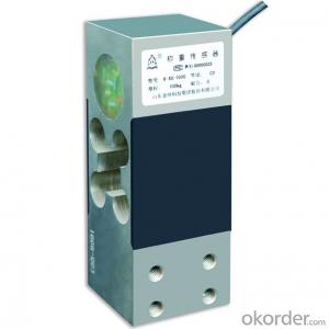


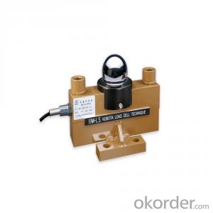
B-XG Type Parallel Beam Structure Load Cell
- Ref Price:
-

- Loading Port:
- Qingdao
- Payment Terms:
- TT OR LC
- Min Order Qty:
- 10 pc
- Supply Capability:
- 500 pc/month
OKorder Service Pledge
OKorder Financial Service
You Might Also Like

B-XG II -××G type load cell (made of alloy steel) is double parallel beam type with small size. The load cell (made of aluminum alloy) is double holed parallel beam type. It is through technology treatment of temperature compensation and adjusting four-corner error. It has low height and small size. It has been conducted four corners adjustment, has good anti-tilting-load, easily for installation and use.
The load cell has high quality and performance, long-term stability and safety. Our company uses the load cell in own platform scale and bench scale, and exports the load cell to various countries such as South Africa, Thailand, Indonesia and Phillipine.
It is suited to produce electronic price computing scale, electronic counter scale, electronic platform scale and other electric scales with small capacities.
The load cell has protection grade specified as IP67. It is able to be used in explosive dangerous circumstance, the explosion-proof symbol is Exia II CT6Ga; ExiaD20T85.


,
- Q:Careful not to pierce the pressure hole, the pressure sensor can continue to use?
- No, you can't punch the pressure hole of the pressure transmitter with sharp things like screwdrivers! It will pierce the corrugated diaphragm, sensor lead to leakage of silicone oil directly damage the sensor. Suggest you buy a new one. Wuhan pine Electric is glad to help
- Q:MPX5010 pressure sensor pin diagram is how, and how to connect the microcontroller?
- MPX5010 has a variety of packages (867B-04, 867C-05, 867E-03, 867F-03), and the order of the pins in different packages is different.MPX5010 uses a single 5V power supply, its working principle is the change of current signal through the film pressure acquisition unit weak, after the film temperature compensation unit complementary temperature compensation, the first stage, after the second stage of realizing potential alignment with supply voltage reference end, and the output pin output.In simple terms, MPX5010 useful pins only three: power input Vs, ground input GND, analog voltage output Vout. Where the Vout output voltage represents the induced pressure, the nominal sensitivity is about 450mV/mm hg.So, if you use a single 5V microcontroller, you can use the built-in or external ADC voltage sampling conversion, by the microcontroller through linear calculation of pressure sensor. If you use 3.3V microcontroller, you need to collect through the external ADC, or first through a more precise amplification adjustment, and then through the built-in ADC acquisition.Specific content, you can go to the official website of NXP, check MPX5010 data book, application notes, and reference design.
- Q:I have a 20000N range pull pressure sensor and an 2000N range amplifier. I think the two are connected. My actual requirement is 2000N, and the 18000N behind the sensor is not required.In the process of calibration, problems were found. First of all, I switched zero. When I applied the force of 500N, the value on the computer was 35N, and then I switched it up. When I was transferred to the value of 98N, I couldn't tune it any more, no matter how the potentiometer turned.Please help me explain the reason for this phenomenon, thank you.
- You can use the 4000N sensor at most, and you can use the 20000N sensor
- Q:How can I amplify the 0-5mv voltage of the resistance strain gauge pressure sensor to 0-5V?
- This small signal high gain amplification generally requires the use of dedicated instrumentation amplifier chips, such as the AD620
- Q:Seeking S7-200 measuring pressure sensor 4-20MA corresponding to the 0-16MPA program
- Although I don't see what it means, I still understand.0mpa corresponds to the output of 4mA; 16MPa corresponds to the output of 20ma. The formula is as follows:(measured pressure /16mpa) * (20-4) +4ma= pressure sensor output current valueI hope I can help you.
- Q:What is the function of the pressure sensor of the LG drum washer? Where is it usually?
- Should be water level sensor, usually have water pipe connection, arranged in the upper part of the machine.
- Q:Can a pressure sensor give two system signals at the same time? It is a 5 meter sensor and a 100 meter sensor. There's only one PLC and one converter. But there are two sets of control loops in the PLC that require sensors to give signals separately. Now change to a 100 meter sensor for the signal. Can the parallel signal terminal be controlled? Is PLC still able to collect signals?
- To see what is your signal, if the signal is the voltage you can try, but do not suggest that you do, after all, are generally two PLC signals from the switching power supply different from the possibility of a burning point. Current signals do not want to, parallel certainly not, and generally PLC, AI points have matching internal resistance, and if the series resistance is too large, your instrument should not be brought up.
- Q:Which eight sensors are on the car? What's the function? A little more detail.
- The air flow sensor detects the intake volume of the engine and controls the injection quantityThe intake pressure sensor detects the intake manifold vacuum and determines the intake volumeThe throttle position sensor detects throttle opening and controls injection speed during accelerationThe camshaft position sensor detects the camshaft position, identifies the top stop point of the cylinder compression stroke, controls sequence, fuel injection and ignitionThe crankshaft position sensor detects the position of the crankshaft and the engine speed, and controls the injection and ignitionThe oxygen sensor detects the oxygen content in the exhaust gas, judges that the mixture is dense and dilute, and correct the air-fuel ratioThe water temperature sensor detects the water temperature of the engine and correct the ignition time and fuel injectionKnock sensor detects whether the engine is knocking, delayed ignition time, and eliminates knock
- Q:Can you tell me how to use the pressure sensor to control the solenoid valve?
- Request to add a display table (with upper and lower alarm control)The formation of PID regulation is not possible because the solenoid valve can only be switched on and cannot be adjusted.The signal of the pressure sensor is transmitted to the display table, and the upper and lower limit alarm is set with the normally opened and normally closed switch of the display table, and the automatic alarm can be realized by setting the upper and lower alarm values.Sibot Technology Department
- Q:How can I use a ABB converter and a pressure sensor to be a constant pressure water supply system?
- The scene using 3 ABB inverter induction motor, a DC010V range for remote pressure 1Mpa table, a 010v range potentiometer, a liquid level sensor, pressure signal to set the desired by the potentiometer, the feedback signal to the HD31 the actual pipe network pressure remote pressure gauge, the reservoir water level sensor monitoring information. HD31 information from the liquid level sensor determines whether the current system continues pumping water from the reservoir. When the reservoir is full of water, the ABB converter operates the potentiometer signal and the remote pressure meter signal through the built-in PID function to achieve the desired pipe network pressure.Adjustment method:(1) wiring in accordance with the above;(2) enabling the water supply expansion function and enabling the water supply expansion card;(3) setting the rated current of water pump 1 according to the motor nameplate;(4) set the command given channel;(5) setting acceleration and deceleration time, analog function and terminal function;(6) ABB frequency converter adjusts two analog signals, and adjusts PID parameters according to actual performance.Adjusted effect:Set the desired network pressure after the start of constant pressure water supply system, through the PID function pump built-in HD31 1 soon change from 0Hz to PID at the upper frequency of operation, has not reached the expected network pressure, more than the pump detection time after the inverter according to the deceleration time preset immediately by the PID on frequency is reduced to a lower frequency, ABB converter at the same time to pump 2 frequency mode is put into use, and then pump 1 again according to PID regulation of the frequency of operation, the observation signal remote pressure gauge feedback stable pressure in the pipe network within the scope of our set in advance.
1. Manufacturer Overview |
|
|---|---|
| Location | |
| Year Established | |
| Annual Output Value | |
| Main Markets | |
| Company Certifications | |
2. Manufacturer Certificates |
|
|---|---|
| a) Certification Name | |
| Range | |
| Reference | |
| Validity Period | |
3. Manufacturer Capability |
|
|---|---|
| a)Trade Capacity | |
| Nearest Port | |
| Export Percentage | |
| No.of Employees in Trade Department | |
| Language Spoken: | |
| b)Factory Information | |
| Factory Size: | |
| No. of Production Lines | |
| Contract Manufacturing | |
| Product Price Range | |
Send your message to us
B-XG Type Parallel Beam Structure Load Cell
- Ref Price:
-
- Loading Port:
- Qingdao
- Payment Terms:
- TT OR LC
- Min Order Qty:
- 10 pc
- Supply Capability:
- 500 pc/month
OKorder Service Pledge
OKorder Financial Service
Similar products
New products

Hot products
Hot Searches
Related keywords

