

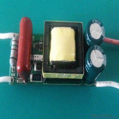

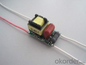
5-7WLED dimmer power NXP IC,0-100% dimming range
- Ref Price:
-

- Loading Port:
- Guangzhou
- Payment Terms:
- TT OR LC
- Min Order Qty:
- 50 pc
- Supply Capability:
- 100000 pc/month
OKorder Service Pledge
OKorder Financial Service
You Might Also Like


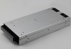
Specification
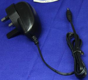
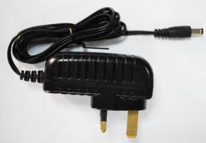
Product model: ZX-G0701-T
Input parameters: AC 50-60HZ
Output parameters: 300mA 15-25DC
Output power: 5W 6W 7W
Dimming range: 1%-100% (applicable to the vast majority of dimming device)
Product size: long * wide * high =40*17*17mm
Product use: This product is suitable for E27 GU10 and other ball bulb lamp controlled silicon dimming lamps and lanterns can be equipped with the shell used in ceiling lamps, etc.
Product features:
2, constant current output
3, with isolated transformer, the human body is more secure
4, the use of import program (NXP2012) design, quality and stability, light adjustment effect of the whole process without flash
5, the life of more than 50000HR
6, with perfect over current, over voltage, short circuit, over temperature, over power protection function
7, with moisture, dust function
8, can be in -40 C, +65 C environment stable work
9, in accordance with the RoHS standard


- Q: How to solve the switching power supply MOS tube and transformer temperature rise is too high
- Switching power supply in the main components of the semiconductor switch tube, power diodes, high-frequency transformers, filter inductors and so on. Different devices have different methods of controlling calorific value. Power tube is a high-frequency switching power supply in one of the larger heat, reduce its heat, not only can improve the reliability of the power tube, and can improve the reliability of switching power supply, improve the average time between failures (MTBF)
- Q: Neighborhoods! Control transformer and switching power supply of the difference, for occasions, advantages and disadvantages
- In the industrial electrical equipment in the control transformer is the primary two-phase AC (AC380V) secondary output 220V or 36V, 24V, 12V AC power frequency transformer, mainly for the AC contactor and drive the use of small AC winding relays. Switching power supply is input AC220V output is required according to the different output DC voltage, in the industrial electrical equipment control circuit is mainly used for the control circuit and relay power supply. Switching power supply output voltage is stable but poor reliability, control transformer life is long but the output voltage by the power grid voltage, the two different principles of the use of different purposes can not be replaced, can not compare advantages and disadvantages.
- Q: What is the difference between what we usually call switching power and ups?
- Switching power supply is a simple power supply, and the transformer power supply name difference. High efficiency and stable operation Wide voltage range. UPS on the complex it includes switching power supply function is different from the power supply. It consists of step-down circuit boost circuit charging circuit detection circuit and battery. It is widely used in emergency power systems, protection of computer information, security for the security system. Remember the crash in Wenzhou? Power failure caused by automatic monitoring paralyzed, and this time on the use of the UPS.
- Q: Note the operating conditions of 220V voltage and the order of switching power supply
- Power failure - electricity - lock - seal ground - warning signs
- Q: Switching power supply
- A voltage is converted to another voltage, the crude pressure is converted to fine pressure
- Q: What are the LLVD and BLVD in the switching power supply?
- (LLVD) a power down; ????(BLVD) secondary power; The so-called power, the second power is on the switching power supply (power cabinet) said. Often, the electrical equipment of the power plant and substation is divided into two main categories: equipment and secondary equipment. A device: refers to the direct use of electrical equipment for the production, transmission and distribution of electricity, through the completion of these equipment to produce electricity and power to the user's task. By a certain device connected according to a certain law for the completion of the power of the hair, change, lose, with the task of the composition of the circuit, known as the electrical main wiring, also known as a circuit or a system. Secondary equipment: refers to the work of a device to monitor, measure, operate and control equipment. The circuit that represents the secondary device interconnection relationship is called secondary wiring, also called secondary circuit or secondary system.
- Q: What is the use of transformer shielded grounding in switching power supply?
- Transformer plus shielding is to prevent electromagnetic interference. Because switching power supply switching frequency is very high, the transformer is a source of interference, shielding it to prevent interference with other components.
- Q: Output + 5V, plus or minus 15V, +24 V, not isolated 15V. Input 85 ~ 220AC, the total power of about 20 watts. I see three kinds of control chip, UC3844 similar products in the most widely used, but the internal non-integrated power tube, peripheral devices are more. VIPER I used the 12, the frequency fixed 60K, so the transformer will be relatively large, PCB also have to do big. I tend to use top223 similar products in almost no use top series, I worry about its stability, and the price of single tube seems to be the highest. These two days the boss will I set down, I hope a master to give pointers. If these three kinds of chips have any other differences also please enlighten, thank you
- No big difference, can be achieved, and the quality can also be designed to have no problem, in fact, you have to from the supply cycle, price and cost to consider, may wish to simply do the cost of three kinds of programs contrast
- Q: What is off-line switching power supply
- You can not take the power, with their own battery switching power supply
- Q: Output 12V2A switching power supply, I would like to change to 12V5A, is not the transformer changed on the line
- Not to change the transformer, but should be the transformer capacity increases
Send your message to us
5-7WLED dimmer power NXP IC,0-100% dimming range
- Ref Price:
-
- Loading Port:
- Guangzhou
- Payment Terms:
- TT OR LC
- Min Order Qty:
- 50 pc
- Supply Capability:
- 100000 pc/month
OKorder Service Pledge
OKorder Financial Service
Similar products
Hot products
Hot Searches
Related keywords

