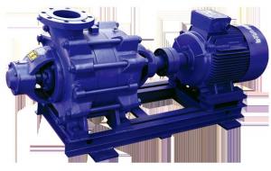


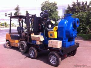
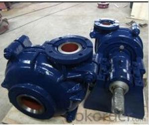
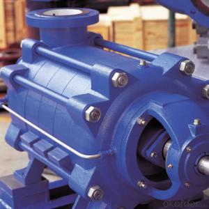
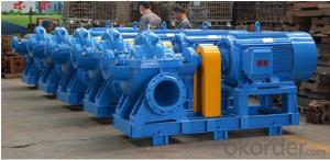
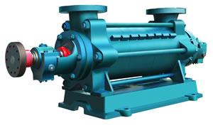
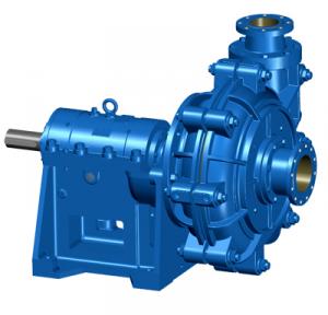
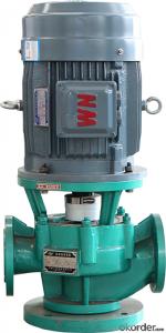
Single- or multistage centrifugal pumps BSX, BRY, BRZS, BRE, BSF
- Ref Price:
-

- Loading Port:
- Shanghai
- Payment Terms:
- TT OR LC
- Min Order Qty:
- 1 pc
- Supply Capability:
- 1 pc/month
OKorder Service Pledge
OKorder Financial Service
You Might Also Like
Design |
Overview of technical data
| Discharge casing material (EN standard) | CC480K; JL 1030 |
| Stage casing material (EN standard) | CC480K; JL1030 |
| Maximum drive rating | 1. 000 kW |
| Diffuser material (EN standard) | JL 1030; CC480K |
| Impeller material (EN standard) | CC480K; 1.4408;1.4593 |
| Type of bearing | Plain bearings |
| Drive frequency | 50 Hz / 60 Hz |
| Maximum speed of rotation | 1. 750 1/min |
| Maximum flow rate | 2. 600 m³/h |
| Maximum discharge-side pressure | 35 bar |
| Suitable for drinking water | Yes |
| Casing material (EN standard) | CC480K; 1.4408;JL1030;1.4593 |
| Suction casing material (EN standard) | JL1030; CC480K |
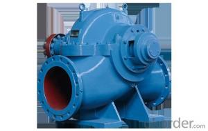
| No. of impeller entries | Single entry |
| Casing material | Cast iron; Bronze;Stainless steel |
| Minimum flow rate | 200 m³/h |
| Suction characteristics | Non- priming |
| Drive voltage | Low voltage, high voltage |
| eClass assignment | 36410000; 36410106;36410100 |
| Other impeller types | Mixed flow |
| Pump set location | Wet well |
| Type of suction casing | Annular casing |
| Max. permissible fluid temperature | 50 °C |
| Type of first impeller | Mixed flow |
| Type of installation | Stationary |
| Type of connection | Flange |
| Type of lubrication | Oil / Product lubrication |
| Type of drive | Electric motor |
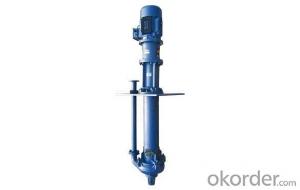
| Installation position | Horizontal or vertical |
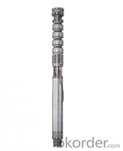
| Borehole diameter (inch) | 16; 24;18;26;20 |
| Shaft material (EN standard) | 1. 4021;1.4462 |
| Type of coupling | Direct |
| Shaft seal type | Mechanical seal; Shaft seal ring |
| Drive | Electric motor |
| Maximum head | 230, 00 m |
| Maximum rated pressure (discharge) | PN 40 |
| Minimum head | 8, 00 m |
| Type of stage casing | Stage casing with diffuser |
| Casing partition | Radially split |
| Connection to power supply | < 6,6 kV, 3~ |
- Q:What is the Rhodes pump?
- The ultimate vacuum of roots pump depends on the pump structure and manufacturing accuracy, and also depends on the limit vacuum of the front pump. In order to increase the limit vacuum of the pump, the roots pump can be used in series. The working principle of roots pump is similar to roots blower. As the rotor continues to rotate, the gas is pumped from the intake air to the space between the rotor and the pump housing V0, and then discharged through the exhaust port. Since the V0 space is fully enclosed after inhalation, the gas in the pump cavity does not compress and expand. But when the top of the rotor turns off the edge of the exhaust and the V0 space communicates with the exhaust side, the gas pressure at the exhaust side is higher, and a part of the gas flows back into the space V0, causing a sudden increase in the gas pressure. As the rotor continues to rotate, the gas is expelled from the pump. Roots pump in the pump cavity, there are two "8" shape of the rotor perpendicular to each other on a pair of parallel axis, by a transmission ratio of 1 of a pair of gear belt movements synchronous reverse movement of each other. In the rotor, the rotor and the pump housing between the wall to maintain a certain gap, you can achieve high speed operation.
- Q:Why does the centrifugal pump start and close first when the outlet valve is closed?
- The operation rules of centrifugal pump strictly required to close the outlet valve before the shutdown, boot and then slowly open the outlet valve, regulating pipeline pressure and current range. The reason is: the centrifugal pump in the startup process in order to avoid large starting current caused by electrical faults, such as circuit breaker tripping,
- Q:Shielding pump is the main drawback of electricity? How much does it cost more than an ordinary centrifugal pump? Is there any noise in the running of the canned pump? How much is it lower than the noise of the common centrifugal pump?
- The ordinary centrifugal pump is driven by coupling the pump impeller shaft is connected with the motor shaft, the impeller and the motor rotates while working and shielding pump is a kind of non seal pumps, pump and motor is sealed in a medium filled by pumping the pressure vessel, the pressure vessel only static seal and, by a group of wires to provide a rotating magnetic field and rotor drive. The structure eliminates the rotary shaft sealing device of the traditional centrifugal pump, so the utility model can be completely free from leakage.
- Q:Water pump outlet valve sequence
- In order to prevent the generation of water hammer when the pump stops the damage to the rubber head, should be immediately set rubber head pump outlet, the gate valve and the check valve is not a very convincing reason to decide the order of habits in our hospital order rubber head, check valve, gate valve1. Check valve located in front of the pump, I do not know what the significance is too great to think of.2. The actual installation sequence shall be: soft fittings, check valves, gate valves. The pressure gauge is best installed on the water outlet of the pump, but it must be in front of the check valve.Reason: 1) the soft joint is used to reduce vibration. The connection between the pump and the piping system, of course.2) normal work, the gate valve is not operating, and the check valve is frequent action, so the probability of maintenance is larger, when the maintenance of the pump closed, the water outlet valve can be maintained without affecting the normal operation of the system.3) the pressure gauge is installed in the check valve, which can prevent the impact and damage of water hammer on the pressure gauge.
- Q:What are the starting and stopping procedures for centrifugal pumps?
- Operation method and operation procedure of self-priming centrifugal pumpClick number: 440 release time: 2011-7-24Centrifugal pump method, centrifugal pump operation steps, centrifugal pump use steps
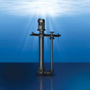
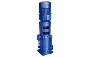
- Q:What are the characteristics of a vertical multistage centrifugal pump?
- A liquid that is primarily diluted, clean, non corrosive, explosive, or similar to water but contains no solid particles or fibers. Because of its high flow and large lift, it is widely used in fire fighting, water supply and air conditioning unit cooling water transportation in high-rise buildings.
- Q:Fire control center manually start the fire pump directly, multi line control, called straight up line NHKVV-7*1.5, my understanding is: straight line from fire control center
- Multi line linkage NHBVR-4*1.5 is a positive pressure blower and smoke exhaust machine fire fighting equipment
- Q:Common failure treatment of piston pump
- Table 15 common troubles and treatment of hydraulic pumpsFault phenomenon, x09 cause analysis, x09 elimination method(1) the pump does not carry oil; the x091. pump does not turn x09 (1); the motor shaft does not rotate1) missed connection power supply2) electrical wiring and component failure, x09 check electrical and troubleshootx09x09 (2) motor heating trip
- Q:How to maintain and repair the booster pump of pipeline pump?
- Two 、 troubleshootingfaultReasonRemoval method1. water pump does not produce waterThe water injected into the water pump is not enough, the rotation direction is not right, and the impeller passage is blocked.Pump water into the pump, pass through the impeller runner, adjust the direction of rotation.2. pump flow is insufficientThe pump speed is too low, part of the blockage, the total lift pump is higher than the rated value, the damage to the impeller.Clean the water pump and pipe, replace the impeller, increase the pump shaft revolutions, adjust the outlet valve.3. lack of outlet pressureThere is air in the liquid, the speed is too low, the impeller is damaged and the outlet valve is open.Exclude liquid air, increase the pump speed, replace the impeller, adjust the small outlet valve.
- Q:What are the advantages and disadvantages of the pump control system and valve control system in the hydraulic system? How to choose in the project?
- Valve control system is generally used for open systems, through the proportional valve or servo valve flow changes to control the motor or cylinder actuator action. The advantages of the system are energy saving, heat generation, and control accuracy. The disadvantage is that the system is complex and the cost is higher.
1. Manufacturer Overview |
|
|---|---|
| Location | |
| Year Established | |
| Annual Output Value | |
| Main Markets | |
| Company Certifications | |
2. Manufacturer Certificates |
|
|---|---|
| a) Certification Name | |
| Range | |
| Reference | |
| Validity Period | |
3. Manufacturer Capability |
|
|---|---|
| a)Trade Capacity | |
| Nearest Port | |
| Export Percentage | |
| No.of Employees in Trade Department | |
| Language Spoken: | |
| b)Factory Information | |
| Factory Size: | |
| No. of Production Lines | |
| Contract Manufacturing | |
| Product Price Range | |
Send your message to us
Single- or multistage centrifugal pumps BSX, BRY, BRZS, BRE, BSF
- Ref Price:
-
- Loading Port:
- Shanghai
- Payment Terms:
- TT OR LC
- Min Order Qty:
- 1 pc
- Supply Capability:
- 1 pc/month
OKorder Service Pledge
OKorder Financial Service
Similar products
New products
Hot products