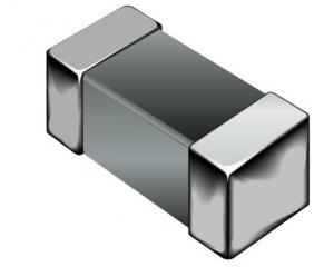
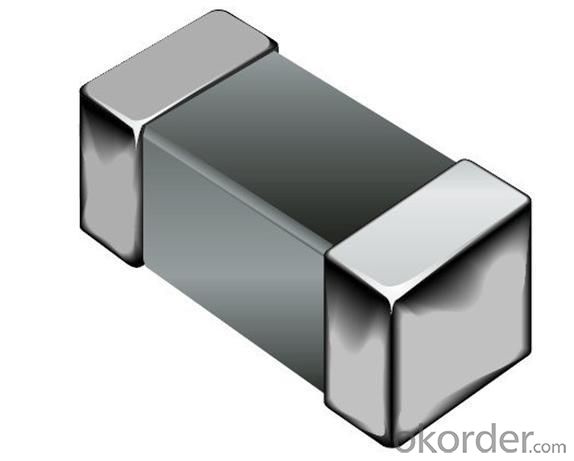
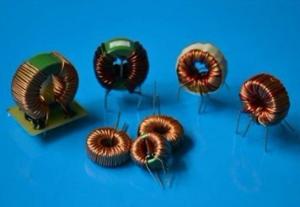
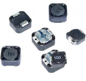
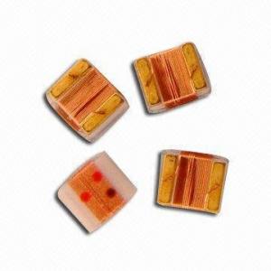
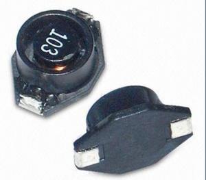
Ferrite Chip Inductors
- Ref Price:
-

- Loading Port:
- China Main Port
- Payment Terms:
- TT or LC
- Min Order Qty:
- 5000 Pieces pc
- Supply Capability:
- 50,000 Pieces per Day pc/month
OKorder Service Pledge
OKorder Financial Service
You Might Also Like
1.ferrite chip inductors
2.leaching resistant rerminations due to metal teb electrodes
3.Coils encapsulated in heat-proof
Features
1.Ferrite chip inductors
2.leaching resistant rerminations due to metal teb electrodes.
3.Coils encapsulated in heat-proof resin make high accurate
4.dimesions and resostant dimensionsand resostant to mechanical shock or pressure.
5.High resistance to heat and humidity.
Applications
Personal computers. Disk drives and comuter peripherals. Telecommunications devices. VCD, DVD and TV circuits,
Test equipment. Electronic control control boards for automobiles.
- Q:An ac generator has a frequency of 5.0 kHz and a voltage of 22 V. When an inductor is conencted between the terminals of this generator, the current in the inductor is 10 mA. What is the inductance of the inductor?
- The reactance is 22/10ma 2200 ohms X? 2πfL 2200 2π(5000)L L 0.070 H or 70 mH .
- Q::)please be as explicit as possible.Thanks!
- Coupled inductors are transformers. In electric circuits coupled inductors are the next step after inductors in circuit analysis. Mutual inductance which is the voltage generated in second inductor by changing current is taught. Coupled circuits analyses is used in RF circuits. Coupled inductors may not be tightly coupled whereas transformers especially power transformers the coupling coefficient is very nearly 1. RF circuits may use lose coupling. And transformers especially power transformers are usually not analyzed the same way.
- Q:A 1.24-?H inductor is connected in series with a variable capacitor in the tuning section of a short wave radio set. What capacitance tunes the circuit to the signal from a transmitter broadcasting at 6.40 MHz?
- First one will have to be king kjors considering he's high contributer of the wrestling part. Second must be gary v seeing that of the years he has watched wrestling. Also others who provide just right customers that don't unsolicited mail or document questions for absalutley no factors.
- Q:I have built a basic telegraph to test the inductor on my scope to verify what I have been taught. I wrapped my coil around a drill bit from bottom to top in a clockwise direction with the negative lead on the bottom, positive on top. I connect the battery positive directly to the top of the coil ( positive) and the negative battery to the key switch, from the switch to the lower end of my coil. I expected as the switch was closed and current was increasing that the coil will attempt to keep it the same ( zero) by reducing the voltage by an equal amount while it is building its magnetic field. However, I am seeing a positive spike rather than a negative and I do not know why. I have connected my scope negative to the bottom of the coil ( negative) and positive to the top of the coil ( positive). Like i said, I expected a negative spike in voltage, but i am seeing a positive spike which reduces to the positive battery voltage. Please Explain ?
- It is a bit difficult to visualize the experimental setup, but what I would expect that you see is this: when you close the key, the voltage across the coil should rise rapidly to the battery voltage, as the current increases, limited only by the coil and battery resistance. The scope will measure the sum of the voltage due to the coil inductance and the coil resistance, the voltage due to inductance will quickly deline to zero, and the voltage will approach the battery voltage asymptotically. Life gets much more interesting when you open the key: the current flowing through the inductor attempts to flow through the opening key contacts and will produce a spark, and you will see a large voltage spike on your oscilloscope. Figure out what the polarity should be, and see if that is what you get.
- Q:Before the switch is closed in a circuit consisting of a 4μC capacitor and 0.2 H inductor, the potential across the capacitor is 200 V. At some instant after the switch is closed, the instantaneous current is 0.7 A. What is the energy in the capacitor at this instant?Answer: 31.0 mJPlease show steps. Thank you.
- Power in watts equals volts x amps
- Q:Describe what happens to the impedance of an inductor at very high frequencies qualitatively.thanks in advance!
- I'm only answering this because it's a very important concept that isn't always clearly stated in the books. DC conditions: Capacitors become open circuits. Inductors become short circuits. AC conditions: Capacitors become resistors that decrease in resistance aka impedance as the frequency increases. Inductors become resistors that increase in resistance aka impedance as the frequency increases. DC is like a frequency of 0Hz so you can see why the DC conditions are as they are.
- Q:Hi, can somebody please help me with this inductor problem? I'm stuck on it and need some help i think that I have the general idea, but need some guidance.
- Hello my old friend, I see you're still trying to penetrate basic electrical theory. Let's see if you're correct here: The relevant equation (the origin of which you can check in any circuitry textbook) is; v(t) L.di/dt where v is the voltage applied to the inductor. Therefore; i (1/L).∫v.dt 500 ? ∫v.dt when v is constant this gives i 500 ? v ? t Because of the step-wise shape of your voltage curve, we have to determine the integral in time-steps: From t 0 to 5μs, i 500 ? 10 ? t so it is the line i 5000 ? t, reaching 25mA after 5μs. From t 5 to 15μs, i drops with a gradient of -5000 from its value of 25mA. In this range it is therefore given by the straight line i 0.05 – 5000 ? t. and it reaches a value of -25mA at t 15μs. From t 15 to 20μs the gradient is again +5000 so that the current is given by the equation: i -0.1 + 5000t so that it rises to a value of zero at t 20μs. This is to be expected since the total postive area (integral) under the voltage curve equals the total negative area, so that the overall integral from 0 to 20μs is zero. In conclusion, I don't know whether you're right or wrong because I don't quite follow your thinking. Anyway the above is how it is! I'm afraid I can't get a sketch into Y!A. I hope you're into BA awards in the meantime! Edit: I'm afraid Steven (notwithstanding his HUGE experience) gets it wrong. For example in the second interval 5 to 15μs he calculates the correct change in current but fails to account for the 25mA flowing at the start of that interval. In the third interval he makes (in principle) the same mistake. He also fails to provide any clue about the current waveform as requested in the question!
- Q:I have a very basic doubt on these topics.av power taken by these over complete cycle is zero.so does that mean a device made up of only L C wont consume any power.also if c l are there wats the point of using resistance thanpls hlp in detail.
- L and C simply store electricity in a magnetic field (L) or electric field (C), only to release that energy later. If L and C are perfect, then you're right, they won't consume power. Practically, though, a real L has some resistance, and a real C has some leakage (conductance, G). If you put DC across an inductor, it will short out, and overheat. If you add a resistor in series, the current will be limited by the resistor, and will not reach too high a current.
- Q:If the current through an inductor were doubled, the energy stored in the inductor would be:halved.quartered.the same.quadrupled.doubled.
- Energy in an inductor (1/2) * L * I^2 If doubled, it becomes (1/2) * L * (2I)^2 which equals: (4/2) * L * I^2 So the energy stored in the inductor also doubles (4/2 2).
- Q:2.An inductor passes 20 mA rms at 12 V rms and 1000 Hz. Calculate the inductance. (95 mH)3.Calculate the inductance of a coil 25 mm diameter, 100 mm long with 30 turns. The core has a relative permeability of 2000. (0.0111 H)Calculate the energy stored when 10 A d.c. flow. (0.555 J) Calculate the reactance for ac with a frequency of 100 Hz. (6.97 ?)Calculate the rms voltage needed to make 10 A rms flow. (69.7V rms)
- 3 question are U mad
1. Manufacturer Overview |
|
|---|---|
| Location | Guangdong,China (Mainland) |
| Year Established | 2010 |
| Annual Output Value | US$10 Million - US$50 Million |
| Main Markets | North America; South America; Eastern Europe; Southeast Asia; Africa; Oceania; Mid East; Eastern Asia; Western Europe |
| Company Certifications | ISO 9001:2000 |
2. Manufacturer Certificates |
|
|---|---|
| a) Certification Name | |
| Range | |
| Reference | |
| Validity Period | |
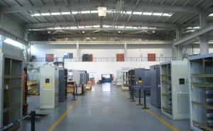
3. Manufacturer Capability |
|
|---|---|
| a)Trade Capacity | |
| Nearest Port | |
| Export Percentage | 41% - 50% |
| No.of Employees in Trade Department | |
| Language Spoken: | |
| b)Factory Information | |
| Factory Size: | |
| No. of Production Lines | |
| Contract Manufacturing | OEM Service Offered Design Service Offered Buyer Label Offered |
| Product Price Range | |
Send your message to us
Ferrite Chip Inductors
- Ref Price:
-
- Loading Port:
- China Main Port
- Payment Terms:
- TT or LC
- Min Order Qty:
- 5000 Pieces pc
- Supply Capability:
- 50,000 Pieces per Day pc/month
OKorder Service Pledge
OKorder Financial Service
Similar products


New products


Hot products

Related keywords

