
U Type Tie Wire/ Utype Iron Wire/ Galvanized U Wire High Quality
- Ref Price:
-

- Loading Port:
- Tianjin
- Payment Terms:
- TT OR LC
- Min Order Qty:
- 5 m.t.
- Supply Capability:
- 10000 m.t./month
OKorder Service Pledge
OKorder Financial Service
You Might Also Like


Item specifice
Bding wire
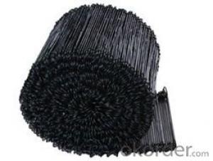
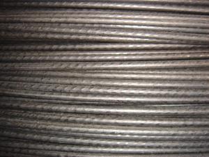
Binding Wire(Stitching Wire), also named Staple Wire, is supplied in sizes from 0.40mm up to 1.00mm, from galvanized iron wire.
We can supply stitching wire, or staple wire on 2 kilo plastic reels, 3 1/2 kilo reels, 10 kilo reels, 15 kilo reels plus spools of 100 kilos.
Stitching wire, or staple wire can be supplied in round or flat wire, in galvanized iron wire or copper coated iron wire.
We can according to the customer's requirements to produce all kinds specs and colors nylon on steel wire, and offer good servicement to customers.
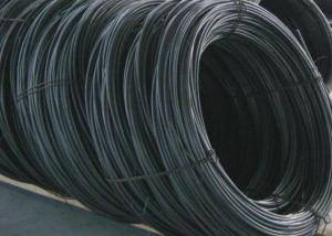
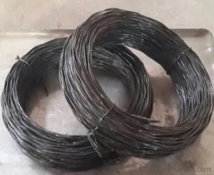
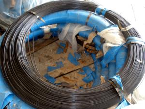
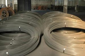
Material: Made by standard low carbon steel wire through the process of wire drawing, acid washing, rust removing and annealing.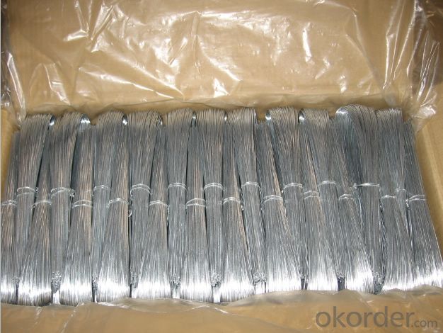
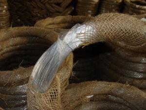
Feature: Can offer excellent flexility and plasticity, can be used widely.
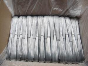
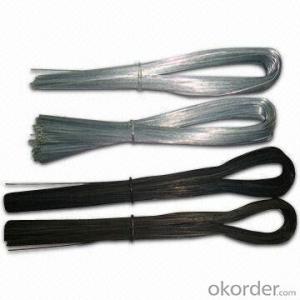
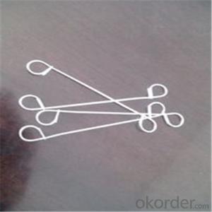
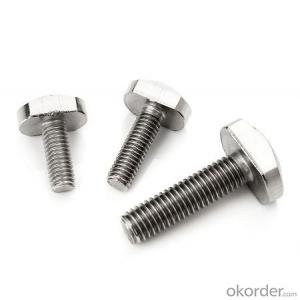
Application: U type iron wire is a kind of tie wire made with iron wire cutting to certain sizes after being straightened. U type iron wire is mainly used as binding material in construction. It is easy for transport and handle, finds popular application in construction, handicrafts or daily use.
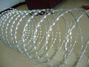
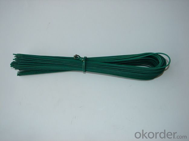
Types: electro galvanized U type iron wire, hot dipped galvanized U type iron wire, pvc coated U type iron wire, black annealed U type iron wire.
Elongation Rate: 10%-25%
Tensile Strength: 30kg-55kg/mm2
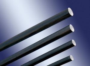
Material | Black annealed wire , galvanized wire |
Cross-sectional shape | Round |
Sectional dimension | 0.6-4.5mm |
Weight | Various specifications to choose |
Length | According to the customer's requirements |
Tensile sterngth | 350Mpa-550Mpa |
- Q:I am wiring a GFCI receptacle with two regular receptacles after it.So before the GFCI I have my 12/2 wire from where it will hook into the box (the line side), after it I have my wire going to the two other receptacles (the load side).Well the GFCI receptacle has screw terminals for the line HOT and WHITE wires as well as a GROUND. On the bottom it has screw terminals for the load side but ONLY the HOT and WHITE, no ground screw.Does this mean that I don't hook up the ground for the load wire or does it mean I have to pigtail the ground to the same screw the line ground is using?I didn't want to assume that I connect the line and load grounds out of fear I was circumventing the GFCI.
- The grounds all are attached to the same ground screw, twist all of the ground wires together and bring one wire to the screw. There are ground wire nuts, green with a hole in the end, put one of the ground wires through the hole and then twist all of the others under the nut.
- Q:I removed my old door chime/bell a few years ago and replaced it with a wireless one. That one quit working and now I am attempting to install a new wired one again. The only problem is, when I removed my old one way back, I failed to label the existing wires to where they go. I have two wires coming out of my wall mount, one white, one brown and the both have a white and red wire sticking out of them. I am not sure which one/ones will connect to the FRONT and TRANS posts on my new chime. I don't have a rear door bell button so that is not a problem. Which wire goes to the FRONT and TRANS and do I cap off any of the 4 wires? My installation instructions don't cover the mindless mistake of not having the wires labled.
- Garage door springs are part of the garage door itself, not the garage door opener. That said, it must also be added that the springs make it much easier to raise and lower the door. They generally last a long time, and they have only one function. But over time, all that lifting, through all those weather changes, tend to weaken the metal and lead to a break. In my case, the springs appeared to be original to the house, which means they've been at work since 1956. Once you understand that long record of service, it becomes a little hard to complain when they finally break down. And break down they did. It was a Sunday afternoon, and we were sitting around the quiet house reading. Suddenly, we heard a large noise that sounded like a very heavy object had fallen on the roof, or maybe a car had driven into the side of the house. I quickly started hunting around for the cause, and couldn't find a thing. So much noise, and no noticeable cause? Didn't make sense . . . until I went out later and tried to open the garage door. Even then, it took me some time to figure out that the spring had split. Once I discovered it (see photo), I knew I'd found the source of the noise. With a broken spring and a solid wood door to a two-car garage, you really can forget about opening the door. I couldn't lift it more than an inch.
- Q:I have this sony x plod headunit that i want to install.unfortunetely i do not know the wiring on it. i could find out as i go along which wires go to which speakers... but which two wires are the POWER wires?so i attached pictures but the basic layout is on the left side there are 4 sets of two wires (im assuming they pair up vertically)on the right side there is a long black wire with a metal hook on the end.
- Black wire with metal hook is the ground. Red connects to switched 12V. (...12V when ignition in RUN or ACC position) Yellow connects to constant 12V. edit: I think the blue wire is for a power antenna.
- Q:I'm trying to hook up my second phone line. I have a red, green and yellow wire in the cable, but no black wire. Is there a reason for this? And what can I do to get the second line up and running? thx
- the wire you have is designed for 1 line only. Back in the day the yellow wire was used to carry ground because ground was necessary for old circuits. Ground is no longer needed so in order to get two lines you need at least a two pair wire (meaning four wires) you might have to run a new wire unfortunately or just keep that one and run another to separate jack.
- Q:The wire I need only comes bare and I would like to try enameling it myself with polyester-imide or polyester-nylon, so that it comes out like magnet wire. What all would I need?
- Enameled wire is copper wire coated with a very thin insulating layer. It is used in applications such as winding electric motor coils, speakers and transformers. It is also used in the construction of electromagnets and inductors. The core material is copper, coated with a thin layer of a polyurethane, polyamide, polyester etc resin - the so-called enamel. For ease of manufacturing inductive components like transformers and inductors, most new enamelled wire has enamel that acts as a flux when burnt during soldering. This means that the electrical connections at the ends can be made without stripping off the insulation first. Older enamelled copper wire is normally not like this, and requires sandpapering or scraping to remove the insulation before soldering.
- Q:I am trying to hook up my motorcycle turn signals but am having trouble with the wiring. Off of each signal stem comes a red wire (positve) and black wire (negative). Then coming form my bike I have a purple wire, blue wire, and green wire. I was messing around with the connections and was able to get all my signals to light up, but not in the fashion i need, like blinking correctly. Any suggestions? Do I need to split the wires? Does one wire go to the left signal and one to the right?
- There are many model specific forums out there that would probably be a better place to ask this question. If this is a common model of motorcycle I would try looking for one. To hazard a guess, the green wire should be split and connected to the black wires. The purple and blue would then be the positive. Trial and error would tell you left and right. If you have a multimeter it would eliminate the guesswork.
- Q:Okay so my question is how would I wire these in a ported box with 2 terminals on each side of the box? Also, is the quot;Bridged Wirefeatured in the diagram negative speaker wire? Thanks.
- It's a misnomer to use the term bridged in wiring subs. They should call it a jumper wire, or something similar. It's a minor detail, but it leads to novices thinking bridging is something done with subs -- it's not, it's the amp. Although since mono amps are becoming more and more common bridging is becoming a thing of the past as mono amps aren't bridgeable. The way I would do it would be to wire each sub to its respective terminal with the coils in series for 4 ohms.
- Q:electroluminescent wire picture?
- What about it?
- Q:could someone teach or explain to me how to hook up the 1st one, i do not understand what is happening there. How do you connect thoes wires to the main wire??? the distribution?
- Ok, first thing you want to do is, for each subwoofer, wire a negative and positive together. You can use regular speaker wire to do that (well you're supposed to anyway). After that, you will have a negative and positive terminal left on each subwoofer. What you need to do is run a speaker wire from each of the terminals, so you have 6 different wires from 6 separate terminals. Make note of the 3 positive wires and the 3 negative wires. Now what you do is simply twist together the 3 positive wires together, so you have 1 positive wire. Connect that positive wire to the positive terminal of the amp (if it's a 1 channel amp. If it's a 2 channel, connect it to a bridged channel on the positive terminal. Or however you want.) Do the same for the 3 negative wires. Twist them together to have 1 negative wire, and connect it to the negative terminal on the amp. Finished! That kind of wiring is called Series wiring, by the way. The other kind is called Parallel wiring.
- Q:On what actually does ampere depends, thickness of wire or number of turns of wire or what else? Electrical
- Your okorder /... and get ohms/1000 ft for the size of wire you select. Also check fusing current while you are there. Eg, #30 has 105 ohms/1000'. So if you have 10' of wire, it's resistance would be 105/100 = 1.05 ohms. Once you have the resistance, use ohms law and the voltage applied to calculate current. For 12 volts, I = 12/1.05 or 11 amps. Fusing current is 10 amps (which is in the open, not in a coil) so you need more length or thicker wire. For AC, and coils, you need more complicated calculations.
1. Manufacturer Overview |
|
|---|---|
| Location | |
| Year Established | |
| Annual Output Value | |
| Main Markets | |
| Company Certifications | |
2. Manufacturer Certificates |
|
|---|---|
| a) Certification Name | |
| Range | |
| Reference | |
| Validity Period | |
3. Manufacturer Capability |
|
|---|---|
| a)Trade Capacity | |
| Nearest Port | |
| Export Percentage | |
| No.of Employees in Trade Department | |
| Language Spoken: | |
| b)Factory Information | |
| Factory Size: | |
| No. of Production Lines | |
| Contract Manufacturing | |
| Product Price Range | |
Send your message to us
U Type Tie Wire/ Utype Iron Wire/ Galvanized U Wire High Quality
- Ref Price:
-
- Loading Port:
- Tianjin
- Payment Terms:
- TT OR LC
- Min Order Qty:
- 5 m.t.
- Supply Capability:
- 10000 m.t./month
OKorder Service Pledge
OKorder Financial Service
Similar products
New products


Hot products