


LX Model Electric Single Beam Suspension Crane, Crane, Single Beam
- Ref Price:
-

- Loading Port:
- China main port
- Payment Terms:
- TT OR LC
- Min Order Qty:
- 1 set
- Supply Capability:
- 100 set/month
- Option:
- Technical Data Technical Data Technical Data Technical Data
OKorder Service Pledge
OKorder Financial Service
You Might Also Like
Item specifice
Profile
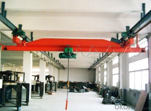
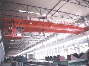
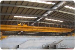
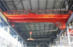
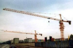
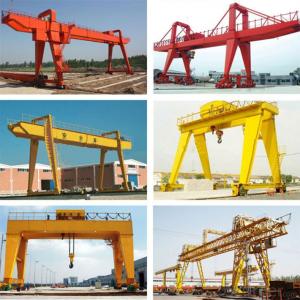
LX Model Motor-Driven Single Beam Suspending Crane is a kind of crane which can running under the track, it is operated mating with CDI and MDI electric hoist to compose a light-small crane with railroad runs. The lifting weight is 0.5T to 10t, the span is 3m to 22.5m, the working grade is A3 to A4, and the working environment temperature is -20 degrees centigrade to +40 degrees centigrade, the working condition must avoid flammable, explosive, hazardous and corrosive. LX Model Motor-Driven Single Beam Suspending Crane is used for loading and unloading in general workshop and warehouse, and the forms of operation are ground handling, remote control, ground handling with remote control.


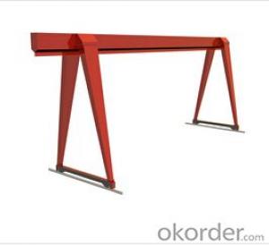
Overall Drawing

Technical Specification
Capacity(t) | Span(m) | Lifting Height (m) | Lifting Speed (m/min) | Machine Power(kW) | Quality (kg) | Max. Wheel Pressure(kN) | Basic Size (mm) | ||||||
H | h | C1 | C2 | A | W | B | |||||||
1t | 4.5 | 6 9 12 18 | 8 | 2.5 | 1120 | 7.9 | 170 | 1513 | 353 377 444 642 | 245 221 332 334 | 750 | 1000 | 1500 |
7.5 | 1381 | 8.7 | 1513 | 1000 | 1500 | ||||||||
10.5 | 1701 | 9.5 | 1513 | 1000 | 1500 | 2000 | |||||||
13.5 | 2000 | 10.3 | 1513 | 2000 | 2500 | ||||||||
16.5 | 2371 | 11.2 | 1513 | 2500 | 3000 | ||||||||
19.5 | 2793 | 12.3 | 1538 | 2500 | 3000 | ||||||||
22.5 | 3343 | 13.7 | 1593 | 3000 | 3500 | ||||||||
2t | 4.5 | 6 9 12 18 | 8 | 4.2 | 1202 | 13.0 | 170 | 1693 | 378 403 465 665 | 262 237 352 354 | 750 | 1000 | 1500 |
7.5 | 1463 | 13.9 | 1693 | 1000 | 1500 | ||||||||
10.5 | 1783 | 14.8 | 1693 | 1000 | 1500 | 2000 | |||||||
13.5 | 2245 | 16.0 | 1718 | 2000 | 2500 | ||||||||
16.5 | 2741 | 17.3 | 1773 | 2500 | 3000 | ||||||||
19.5 | 3194 | 18.4 | 1793 | 2500 | 3000 | ||||||||
22.5 | 3880 | 20.2 | 1828 | 3000 | 3500 | ||||||||
3t | 4.5 | 6 9 12 18 | 8 | 5.7 | 1305 | 17.5 | 170 | 1798 | 523 549 640 843 | 417 391 468 471 | 750 | 1000 | 1500 |
7.5 | 1599 | 19.2 | 1798 | 1000 | 1500 | ||||||||
10.5 | 1955 | 20.2 | 1798 | 1000 | 1500 | 2000 | |||||||
13.5 | 2425 | 21.5 | 1878 | 2000 | 2500 | ||||||||
16.5 | 2950 | 22.8 | 1898 | 2500 | 3000 | ||||||||
19.5 | 3505 | 24.3 | 1933 | 2500 | 3000 | ||||||||
22.5 | 4010 | 25.6 | 1933 | 3000 | 3500 | ||||||||
5t | 4.5 | 6 9 12 18 | 8 | 9.1 | 1690 | 28.0 | 170 | 2013 | 566 579 679 889 | 416 403 529 536 | 750 | 1000 | 1500 |
7.5 | 2044 | 30.4 | 2013 | 1000 | 1500 | ||||||||
10.5 | 2519 | 31.8 | 2063 | 1000 | 1500 | 2000 | |||||||
13.5 | 3131 | 33.5 | 2118 | 2000 | 2500 | ||||||||
16.5 | 9.9 | 3864 | 35.4 | 200 | 2150 | 2500 | 3000 | ||||||
19.5 | 4761 | 37.7 | 2170 | 2500 | 3000 | ||||||||
22.5 | 5483 | 39.6 | 2200 | 3000 | 3500 | ||||||||
10t | 4.5 | 9 12 18 24 | 7 | 16.2 | 2426 | 49.6 | 200 | 2445 | 736 826 1006 1189 | 736 826 1006 1189 | 750 | 1000 | 1500 |
7.5 | 2798 | 55.3 | 2445 | 1000 | 1500 | ||||||||
10.5 | 3472 | 58.2 | 2500 | 1000 | 1500 | 2000 | |||||||
13.5 | 4341 | 61.1 | 2560 | 2000 | 2500 | ||||||||
16.5 | 5158 | 63.5 | 2570 | 2500 | 3000 | ||||||||
19.5 | 6129 | 66.3 | 2715 | 2500 | 3000 | ||||||||
22.5 | 7525 | 70.0 | 2720 | 3000 | 3500 | ||||||||
Product features
The electric suspension crane’s bridge frame is mainly composed of main beam and cross beam. The main beam is the main load-bearing component of the crane, and the bottom flange is the running track of the electric hoist. The structure are U-shape groove rolled by steel plate, inclined plate, rib plate and I-beam group to weld to solid web girder or built-up beam by I-beam and U-bar. Single hole hinge connecting plate be designed at the span of main beam, adopt blanking from numerical control cutting machine and boring to process; After connect the end beam, the force balance of each wheel group is reached. According to different spans, the electric suspension crane’s bracket is designed with 500mm, 750mm and 1000mm; the negative wheel pressure is not allowed on the opposite side, when the electric hoist runs full load to the end of bracket. Ends of both sides of main beam are designed with trolley running block and buffer. The main beam is made arch as requires, camber F should be (1/1000~1.4/1000)S, the maximum camber shall be in the middle of span ( within S/10 ). The cross beam device is located above on the both sides of main beam. Through the single hole hinged connecting plate to connect main beam, the structure is welded by the channel steel, the strengthening plate and the connecting plate group. Trough the boring and milling machine to process pinhole what connecting travelling trolley from both sides by one off, fully guarantee the machining accuracy. Each of the two pinhole installed a triangular balance beam connecting plate to connect the electric trolley. Three pinhole fixed with end beam by card board, make it easy and convenient. Rubber buffers are installed at both ends of the beam to avoid structural parts damaged by collision. Adopt balance shaft to connect structure between the main beam and the end beam, the utility model has the advantages of simple structure, convenient installation and convenient transportation and storage.
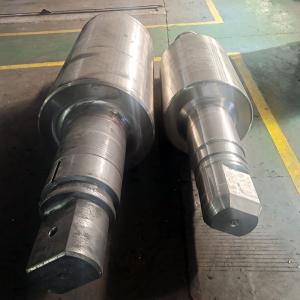
The cart travelling mechanism of the electric suspension crane’s configuration are two sets of active travelling trolley, two sets of slave travelling trolley, the two bolts connect with the end beam connecting plate under the wall plate. Active travelling trolley is composed of running motor, speed reducer, wall plate, drive and driven wheel group, flat nut, bolt and adjusting pad. The motor adopts braking motor, the standard motor insulation class is B class insulation, the protection grade is IP44, and also can be made into F and H class insulation according to the working conditions, the protection grade is IP54 and IP55. The box cover, box body of driving device are casted of good anti vibration performance gray iron (HT200). The gear and gear shaft are 40Cr die forging, through rough car, quenching and tempering treatment, fine car, hobbing to process, the hardness is up to 235 ~ 269HB. Wheel group is 45# steel die forging, through rough turn, quenching, tempering and finish turning to process.


1. Manufacturer Overview |
|
|---|---|
| Location | |
| Year Established | |
| Annual Output Value | |
| Main Markets | |
| Company Certifications | |
2. Manufacturer Certificates |
|
|---|---|
| a) Certification Name | |
| Range | |
| Reference | |
| Validity Period | |
3. Manufacturer Capability |
|
|---|---|
| a)Trade Capacity | |
| Nearest Port | |
| Export Percentage | |
| No.of Employees in Trade Department | |
| Language Spoken: | |
| b)Factory Information | |
| Factory Size: | |
| No. of Production Lines | |
| Contract Manufacturing | |
| Product Price Range | |
Send your message to us
LX Model Electric Single Beam Suspension Crane, Crane, Single Beam
- Ref Price:
-
- Loading Port:
- China main port
- Payment Terms:
- TT OR LC
- Min Order Qty:
- 1 set
- Supply Capability:
- 100 set/month
- Option:
- Technical Data Technical Data Technical Data Technical Data
OKorder Service Pledge
OKorder Financial Service
Similar products
New products
Hot products
Related keywords

