
IEC STANDARD BARE COPPER STRANDED CONDUCTOR 25MM2
- Ref Price:
-

- Loading Port:
- Tianjin
- Payment Terms:
- TT OR LC
- Min Order Qty:
- 1000 m.t.
- Supply Capability:
- 100000 m.t./month
OKorder Service Pledge
Quality Product, Order Online Tracking, Timely Delivery
OKorder Financial Service
Credit Rating, Credit Services, Credit Purchasing
You Might Also Like


Quick Details
Place of Origin: Jiangsu, China (Mainland)
Model Number: BCC 25MM2
Type: High Voltage
Application: Power Station
Conductor Material: Copper
Packaging & Delivery
| Packaging Details: | wooden drum packing |
|---|---|
| Delivery Detail: | 7 days |
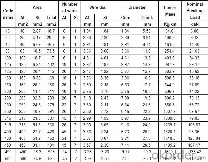
Specifications
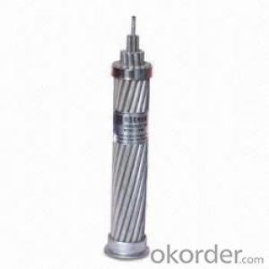
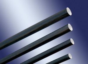
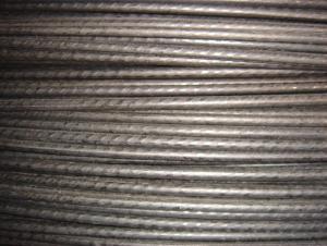
HIGH VOLTAGE BARE COPPER CONDUCTOR CABLE 25MM2
1 GOOD PRICE AND QUALITY
2 SHORT TIME DELIVERY
HIGH VOLTAGE BARE COPPER CONDUCTOR CABLE
APPLICATION
For use on insulators for overhead distribution or for ground conductors
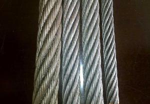
CONSTRUCTION
Soft or annealed, bare or tin coated, solid or concentric stranded copper conductor.
- Q:voltage regulater wires get hot when bike runs 86 yamaha v max. why do they do this?
- If the wire connectors at the regulator are corroded or not making a good connection, that can cause the wires to get hot. On my Kaw, I ended up having to remove the connectors and solder the ends together to keep them from getting hot enough to melt the plastic surrounding the connectors.
- Q:at least 3 examples for wire and wireless......
- Wire simplex: Serial data from GPS to PC or autopilot using 2 wires. Wire, half duplex: Theatrical intercom, with push to talk buttons for each spotlight operator. Wire, full duplex: telephone. Wireless, simplex: infrared remote control for TV. Wireless, half duplex: walkie-talkie, family radio service, cb radio. Wireless, full duplex cellphone, cordless phone.
- Q:I have two alpine 1242d. I need to wire them parallel parallel. Ive seen many pictures on how to do it but im still a little confused. Okay first off do i need any special type of wiring or will my 4awg wire work. Because it shows multiple wire connections where the wires combine. The positive connect from an existing wire already running to the amp. If anyone understand what i mean can you explain it to me. Thank you much appreciated!
- First off, your 4 awg wire will work for powering your amp but its right on the edge, I would go with 1/0 if your amp terminals will accept that gauge. Second, you don't have to make all those connections with one speaker wire, that diagram is simply showing you the current path. If you want a really simple way to do this, cut three strips of speaker wire and strip the ends about 3/8 of an inch. stick one end of each positive wire into one of the positive terminals on any voice coil. now run one wire to the + amp terminal, one wire to the other + voice coil on the same sub, and one wire to either of the + voice coil terminals on the other sub. now strip a fourth wire and connect the two + terminals on the second sub. repeat the same procedure for the - terminals. I reccomend using 14 or 16 gauge speaker wire for this. Good luck
- Q:well i've been asking for quite sometime on the correct wiring of a bathroom fan up to the same circuit as my light in the bathroom but i believe i've figured out. but i have a question now about the wire guage.the wire guage in the house is the standard solid 12 or 14 i think(house built in 50's) and the the wire that came with the bathroom fan looks a little smaller or about same size but it's braided .it should be fine to splice the two right?
- Yes. it's ok. Also. the wiring you have is probably 12 gague. Newer homes use 14 gague wiring for lighting to save some money.
- Q:i bought a programmable thermostat, and the wiring i see doesn't make any sense. it's for central air, heating and cooling. there are no tags or labels on the wires, and it was probably installed in the seventies.there are four wires coming out of the wall, and they're screwed into four of six slots:Y = blue wireG = red wireW = green wireR = white wireB = emptyO = emptythe new thermostat has the following slots: G, Rc, Rh, Y/O, W/B, Y1. how should the old labels correspond to the new ones?
- Here is the schematic you will need. First off I will explain what each terminal is for. Y is for cooling. G is for fan operation. W is for heating operation. R is for your 24 volt transformer. A typical wiring color is as follows. R= red wire. G= green wire. Y=yellow. W=white. B and O are for a heat pump. Do not use them. Now what you will have to do is make sure the wires at the furnace are set the way described above. Make sure if you have to switch wires around on the furnace that the power is off. You WILL blow the low voltage fuse on the control board. If your furnace has a C terminal that is the COMMON That is used to power your thermostat. (so you don't have to use batteries). You will need a 5th wire for that. For the life of me I cant figure out why they did not put the proper color wires on the right terminals. It's a supper easy thing to change. Just remember to turn off the power before removing any wires. If you use this diagram, then it will be simple for anyone else to work on the system . I hope this helps. If you need any further information feel free to let me know and I will do my best to answer your questions. Good luck.
- Q:just need a little help to make right.just wiring an outlet from building to breaker box outside.. which way is the right way to wire it to a breaker then the box. Got the right breaker. Thanks
- This doesn't sound like an easy answer without seeing it. For instance, how long is the wire run; is it entirely outside (if so, then you'll need either conduit for the full run, or UF-B rated wire buried below the freeze line with conduit where it exits the ground to the Service Panel). Outside receptacles should also be GFCI (Ground Fault Circuit Interrupter) protected. A single pole 20amp breaker should be used for a 12/3 wire. Load wire (black) goes into the screw of the breaker; the neutral (white) wire screws into the neutral bus bar of the service panel (breaker box), and the bare ground wire screws into the ground bus bar. Since these wires are interchangeable, it really doesn't matter which side of the panel you hook the neutral and ground wire to. BE CAREFUL!!!!! The main bus bars can still be hot (charged) even with the power turned off. If you ground yourself and touch the wrong thing, you'll be wondering what went wrong from the great beyond. Get a basic electricity book from Home Depot, or look on youtube. If you're not 100% confident, please leave this to a professional.
- Q:If someone were holding onto a high-voltage wire by both hands, why would his/her body have the same potential as the wire? How come his/her body would attain the same potential as the wire?
- Any open ended conductor (a human body in this case) making contact with another conductor will automatically attain the same Voltage potential as the other conductor with respect to the opposite terminal of the source Voltage that supplied the Voltage. For example if you make good contact with your finger to the positive terminal of a 12V battery then that puts your whole body at 12 Volts above the negative terminal of that battery. Two conductors in contact with each other will always be at the same Voltage potential at the point of contact. The fact that both hands are on the wire makes no difference because the resistance of the high Voltage wire between the hands is so small compared to the resistance through a human body from one hand through the chest and out the other hand that all the current if any would go through the wire and not through the human body. If however the wire was cut in two at any point between the two hands then one hand would have the full positive source voltage and the other hand would be at reference 0 Volts. Consequently the body would most likely immediately burn to a crisp due to the current through the body. If the body did not disintegrate and current continued to flow through it then a Voltage gradient would be established from one hand to the other with one hand at full wire Voltage and the other hand at 0 Volts.
- Q:I need to get to the audio wiring
- you cannot simply go with matching the colors factory radios have extra wires that are not needed with an aftermarket install most of the time (wires that control the dimmer on the radio, speed sensitive volume) you will need three power wires (constant, ignition, and ground), plus your speaker wires use a test light to test your wires, usually at the radio the yellow wire is your constant, the red is your ignition, and black is always ground to find your constant use the test light, it will be hot at all times so that your radio can remember the time, and your settings- next you need your ignition, it is only hot when the key is on or in the accessory position, to tell the radio when to come on- the ground is self explanatory to find which wires go to what speakers all you need is a 9v battery, put the positive end to a wire and test all of the other wires to the negative side and you will hear a crackling noise from a speaker when you have the right combination
- Q:trying to install aftermarket side mirrors w/turn signals and don't know where to locate the turn signal wires.it's for an 06 chevy cobalt LS automatic.Also is it okay to use electrical tape on the wires themselves after connecting them?
- The wires should never be spliced and taped with electrical tape on a car. It gets brittle, cracks, unwinds with age. Problems in the future. Go to a local audio installer or Best Buy even and look for wire taps. Do it right and avoid trouble in the future like when you hit a puddle, car wash or winter storm. Find the wire going to the front turnsignal and trace it back as far as you can. Then install the wire taps and run the wires to your mirrors using the same channel the mirror controls and window, door lock power comes through. Luck Roy G KC
- Q:I have a water valve that I need to connect but I don't know how to read this diagram. I'm unsure how to connect the wires to the cold and hot valve. I have four wires that need to be connected. A pair of white caps with one blue wire and one orange; and a pair of black caps with one blue wire and one yellow wire. Sorry if this sounds confusing but I have no idea how to explain it well. Thanks!
- In the diagram, there are two cold valves: valve 1 has a yellow wire to it; valve 2 has a blue and a yellow wires to it...............you may have to contact the washer manufacturer or the company that makes the valve for better installation instructions ( it's possible that all of the wires are not used in both valves )
1. Manufacturer Overview |
|
|---|---|
| Location | |
| Year Established | |
| Annual Output Value | |
| Main Markets | |
| Company Certifications | |
2. Manufacturer Certificates |
|
|---|---|
| a) Certification Name | |
| Range | |
| Reference | |
| Validity Period | |
3. Manufacturer Capability |
|
|---|---|
| a)Trade Capacity | |
| Nearest Port | |
| Export Percentage | |
| No.of Employees in Trade Department | |
| Language Spoken: | |
| b)Factory Information | |
| Factory Size: | |
| No. of Production Lines | |
| Contract Manufacturing | |
| Product Price Range | |
Send your message to us
IEC STANDARD BARE COPPER STRANDED CONDUCTOR 25MM2
- Ref Price:
-
- Loading Port:
- Tianjin
- Payment Terms:
- TT OR LC
- Min Order Qty:
- 1000 m.t.
- Supply Capability:
- 100000 m.t./month
OKorder Service Pledge
Quality Product, Order Online Tracking, Timely Delivery
OKorder Financial Service
Credit Rating, Credit Services, Credit Purchasing
Similar products
New products
Hot products