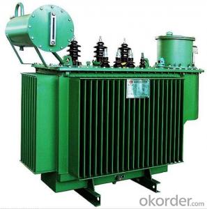
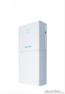
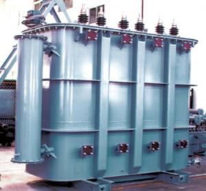
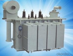
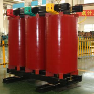
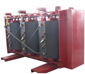
high-voltage Class 10KV S11 series transformer
- Ref Price:
-

- Loading Port:
- Shanghai
- Payment Terms:
- TT OR LC
- Min Order Qty:
- -
- Supply Capability:
- 1000sets set/month
OKorder Service Pledge
Quality Product, Order Online Tracking, Timely Delivery
OKorder Financial Service
Credit Rating, Credit Services, Credit Purchasing
You Might Also Like


| Rated capacity (KVA) | Voltage | connection group tab | Loss | unload current(%) | resistant voltage | weight | Measure(MM) | Distance of Din rail | |||||||
| high-voltage(kv) | extend connection | low-voltage(kv) | unload | load | empty weight | oil weight | total weight | length(L) | width(W) | height(H) | cross(M)×length | ||||
| 30 | 6 | ±5% (±2×2.5%) | 0.4 | Yyn0 | 100 | 600 | 2.1 | 4 | 215 | 85 | 375 | 965 | 700 | 1060 | 400×450 |
| 50 | 130 | 870 | 2.0 | 275 | 90 | 440 | 995 | 735 | 1085 | 400×450 | |||||
| 63 | 150 | 1040 | 1.9 | 345 | 115 | 565 | 1085 | 7058 | 1315 | 400×450 | |||||
| 80 | 180 | 1250 | 1.8 | 345 | 100 | 530 | 1005 | 755 | 1125 | 400×450 | |||||
| 100 | 200 | 1500 | 1.6 | 395 | 105 | 590 | 1020 | 775 | 1130 | 400×450 | |||||
| 125 | 240 | 1800 | 1.5 | 445 | 110 | 665 | 1035 | 770 | 1190 | 400×450 | |||||
| 160 | 280 | 2200 | 1.4 | 510 | 120 | 745 | 1115 | 780 | 1205 | 550×550 | |||||
| 200 | 340 | 2600 | 1.3 | 585 | 140 | 875 | 1270 | 740 | 1225 | 550×550 | |||||
| 250 | 400 | 3050 | 1.2 | 690 | 160 | 1035 | 1380 | 840 | 1335 | 550×550 | |||||
| 315 | 480 | 3650 | 1.1 | 805 | 175 | 1165 | 1370 | 775 | 1395 | 660×660 | |||||
| 400 | 570 | 4300 | 1.0 | 955 | 200 | 1400 | 1450 | 895 | 1440 | 660×660 | |||||
| 500 | 680 | 5150 | 1.0 | 1120 | 225 | 1610 | 1495 | 905 | 1500 | 660×660 | |||||
| 630 | 810 | 6200 | 0.9 | 4.5 | 1335 | 265 | 1935 | 1575 | 980 | 1685 | 660×660 | ||||
| 800 | 980 | 7500 | 0.8 | 1675 | 335 | 2410 | 1665 | 995 | 1795 | 820×820 | |||||
| 1000 | 1150 | 10300 | 0.7 | 1855 | 380 | 2755 | 1770 | 1160 | 1855 | 820×820 | |||||
| 1250 | 1360 | 12000 | 0.6 | 2205 | 445 | 3260 | 1825 | 1235 | 1915 | 820×820 | |||||
| 1600 | 1640 | 14500 | 0.6 | 2515 | 535 | 3905 | 1855 | 1300 | 2000 | 820×820 | |||||
- Q:I know that the ratio of primary turns to secondary turns is the multiplying factor in voltage. So if you wanted 100,000 volts from a 10 volt source could you potentially do this:4 transformerseach transformer has 10 coils in primary and 100 in secondaryThe output of each transformer's secondary is connected to the primary of the next transformer so that you get 10*10*10*10 or 10,000 as your multiplying factor.Would this work?or do you have to do it the hard way and wind 10 coils in the primary of a single transformer and wind 100,000 times in the secondary?
- Yes, you can cascade transfomers. The efficiency might be lower, but it will work to a point. Note also that the current will be proportionally lower. The main problem will be the insulation strength as the voltages get higher: if the insulation isn't strong enough arcing will happen. That 100kV stage needs to be very, very robust - in fact, it probably isn't even feasible at a 1:10 turns ratio because its primary voltage is too high (10kV) and so will need ridiculously thick insulation and/or a lot of turns - engineering such a beast is certainly beyond the casual experimenter. The smart money says forget it. There's lots of ways to generate high voltage besides cascaded transformers. Techniques using flyback coils and capacitive discharge for example can easily get you to 50kV or more (this is, for example, how a Taser makes its HV.) I've included some links below. And please, be very, very careful this stuff can kill you.
- Q:630 kilovolt transformer secondary side of the current is how much
- 630kVA that his rated capacity, it is ideal to say that with the load of 630kW (but actually can not bring so much) Rated current calculation formula: rated current = capacity / rated voltage / root number 3 (for 3-phase transformer) 630 / 0.4 / 1.732 = 909.3 A Pure hand to play, hope to adopt ~
- Q:TN-S system in the transformer neutral point that pe line and n-line neutral point how to take? N line and pe line in the neutral point on the connected, and then ground the same ground? Or that n line from the neutral point out of their own then a pe line then one after another? If the neutral point out of the ground, in the three-phase imbalance when the n-line current?
- TN-S way power supply system It is the work of the zero line and dedicated protection line PE strictly separate power supply system, N line and PE line in the transformer working ground once separated, not to re-connect. Called TN-S power supply system. The TN-S power supply system is characterized as follows. 1) When the system is running normally, there is no current on the dedicated protection line, but there is an unbalanced current on the working zero line. PE line to ground no voltage, so the electrical equipment metal shell connected to zero protection is connected to the dedicated protection line PE, safe and reliable. 2) The working zero line is used only as a single-phase load circuit. 3) Dedicated protection line PE is not allowed to break, but also not allowed to enter the leakage switch. 4) the use of leakage on the trunk protection, the work of the zero line shall not have repeated grounding, and the PE line has repeatedly grounded, but not through the leakage protection, so TN-S system power supply lines can also be installed on the leakage protection. 5) TN-S power supply system is safe and reliable, suitable for industrial and civil construction and other low-voltage power supply system. In the construction work before the "three links and one leveling" (Dentsu, water, road and ground level - must use TN-S way power supply system.
- Q:Parallel can provide the total capacity is not the sum of the capacity of the two transformers, or how to calculate? What is the principle of allocation of load load, that is, how to allocate two transformer load capacity?
- If the transformer voltage ratio is equal (equivalent to the equivalent of the induced potential), the impedance voltage (equivalent to the transformer internal resistance) are equal, then they output the current is equal, that is, the load is evenly distributed. The total capacity is the sum of their capacity. Otherwise, the impedance of the output voltage of the small current, its load rate is relatively high, when its load current reaches full load, the impedance voltage has not reached a full load, if the load at this time for the total Capacity, then the total capacity is less than the sum of the two capacity. This is a strict argument. In fact, the two transformers of the impedance voltage difference is very small, the load distribution is also very small difference, in addition, the so-called transformer is a little overload, nor is it so strict, so the actual total capacity and the difference between the two capacity Not big. In order to prevent the load distribution is too uneven, the capacity of these two transformers should be as close as possible, should not exceed 3: 1, because the capacity of the large impedance voltage is small, it has reached full load, and that small capacity is still in the owe Load, its role is not fully play out, it is not the significance of the parallel. The above is the answer 2009-10-8 02:31. At the end of the said, "the large capacity of the impedance voltage is small, it has reached full load, and that small capacity is still in the obvious underload, its role is not fully play out", wrong, apologize. Should be large capacity transformer impedance voltage, and small capacity impedance voltage is small, the load rate is high, the output current to reach full load, resulting in a larger capacity of the transformer can not put its big capacity advantage fully play out, this is Very unfavorable.
- Q:I hate feeling the need to justify myself, but I've seen a lot of answers telling askers to do their own homework. I'm trying to do so, but can't find any equations in the book relating power to voltage as well as turn number. Is it PviN? I've just seen Pvi, but that wouldn't apply to multiple loops. This is for ideal transformers by the way, so power for the secondary and primary coils is the same right? But are their vi's equal, or their viN's?The primary coil of a transformer has 200 turns and the secondary coil has 800 turns. The power supplied to the primary coil is 400 watts. What is the power generated in the secondary coil if it is terminated by a 20-ohm resistor?
- The turns ratio is 4:1 of the primary. The power supplied to the primary is 400W. So regardless of anything else, in a ideal transformer, 400W is available on the secondary. But voltage will be 4x higher, current 4x smaller, than the voltage and current in the primary. Disregarding all that, if there is 400W of power flowing in the primary, then 400W will be being dissipated in the 20 ohm resistor. Watts in watts out, but secondary load (resistance) controls the wattage. There is no way to tell the output voltage and current, without knowing the input voltage and current. But whatever they are, the product of voltage x current will be 400W, in this instance.
- Q:I'm an intern at an aluminium smelter and am part of the power plant there. They replaced the 33 kV transformers with the 132 kV ones because of an increase in the demand from the smelter. But what are the advantages of such a replacement, besides the obvious decrease in heat loss?
- The new transformer is connected to the transmission grid at higher voltage level (132 kV) vs the old one (33 kV). This implies the increase in power rating (MVA). The old voltage level 33kV was too low for supplying the increased power demand. In addition, by removing the 33 kV voltage level, one step in the transmission chain has been removed. I am assuming that, in the old configuration, in addition to 11/33 kV transformation there was a 33/132 kV voltage transformer(s) somewhere between the smelter substation and the high voltage transmission grid. Three main benefits are: higher capacity, lower losses and minimization of number of voltage levels in the substation reduced costs of operation and maintenance.
- Q:For example, if you have a battery that puts out 1 amp, can you use a step down transformer to turn that into 1000 Amps. Or is there some sort of limit to how much one can increase current in a circuit?
- Transformers do run on AC, but they step current and voltage up or down along with some heat losses. Theoretically there is no limit to the stepping up of current, but it has to be inline with the magnetic saturation of the primary and secondary coils. In other words you can't put in one turn in the primary with one amp and in the secondary have 1000 turns and expect a 1000 amp outlet current. You have to to base the primary circuit on how much magnetic flux it can produce with how many turns of wire. Like maybe 1000 turns in the primary and 1 million turns in the secondary will get that thousand amps. Plus you have to make sure you have the laminated silicon steel plates that can handle all the eddy currents from the fluctuating alternating magnetic fields and the heat that produces. But anyway, to my knowledge there is no limit to stepping up or stepping down current or voltage as long as you size the wires and core properly to handle the load running thru it
- Q:I have a small question concerning flyback transformers. I have run into some confusing problems when i tried testing the flyback using the High voltage power supply project
- You might find whether your transformer is broken with an ohmmeter between the ultor cap and a pin by trying each with the meter set to a high ohms range, with (I think) the black meter lead connected to the ultor. If you don't see a result 1st. time around, try swapping the meter leads. If you get a result, try the 24V test there. If you don't, and using his method also fails, I think you have a dud. So far as the 9V test, I think that has a fatal flaw. A digital multimeter, or usually also an analogue one, cannot respond fast enough to a single pulse. A digital meter only samples at a certain rate, and if the voltage does not align with the sampling, you see nothing. Even if it does, I think you would only see an instantaneous reading before next sample sees nothing. Apart from that, the voltage spike will be well over 200V! The object is to sort out input direction in the primary. I would suggest you sort out the primary connections, and build the circuit. I have not looked at it, but I think if you fire it up, you will either have + HV coming from the ultor cap, or nothing. If nothing, reverse the primary. DON'T TEST IT WITH YOUR FINGERS!!!
- Q:A 2300/230 V step down transformer is rated at 70 kVA and 60 Hz. Its windings have the following resistances and inductances : Rp 0.093 ohms, Xp0.280 ohms, Rs 0.00093 ohms and Xs 0.00280 ohms. The transformer's rated current at the secondary is 3261 A. Assume that a10 from 2300/230 V and calculate the no load voltage for unity 0.7 lagging and 0.7 leading power factor.
- this is quite a typical question. there will be many examples similar to it
- Q:How do I choose a transformer? The
- According to the nature and size of the load to determine the capacity of the transformer. The ratio is selected according to the supply voltage and the voltage required for the load.
1. Manufacturer Overview |
|
|---|---|
| Location | |
| Year Established | |
| Annual Output Value | |
| Main Markets | |
| Company Certifications | |
2. Manufacturer Certificates |
|
|---|---|
| a) Certification Name | |
| Range | |
| Reference | |
| Validity Period | |
3. Manufacturer Capability |
|
|---|---|
| a)Trade Capacity | |
| Nearest Port | |
| Export Percentage | |
| No.of Employees in Trade Department | |
| Language Spoken: | |
| b)Factory Information | |
| Factory Size: | |
| No. of Production Lines | |
| Contract Manufacturing | |
| Product Price Range | |
Send your message to us
high-voltage Class 10KV S11 series transformer
- Ref Price:
-
- Loading Port:
- Shanghai
- Payment Terms:
- TT OR LC
- Min Order Qty:
- -
- Supply Capability:
- 1000sets set/month
OKorder Service Pledge
Quality Product, Order Online Tracking, Timely Delivery
OKorder Financial Service
Credit Rating, Credit Services, Credit Purchasing
Similar products


New products


Hot products


Related keywords

