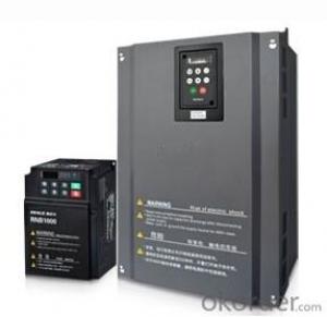
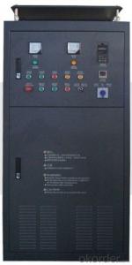
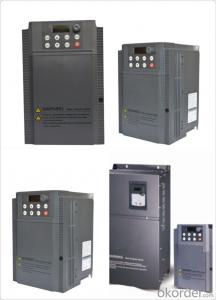
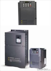
Frequency Inverter Single-phase 380V class 215KW
- Ref Price:
-

- Loading Port:
- Tianjin
- Payment Terms:
- TT OR LC
- Min Order Qty:
- 1 pc
- Supply Capability:
- 100000 pc/month
OKorder Service Pledge
OKorder Financial Service
You Might Also Like

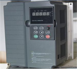
General
CNBM frequency inverter is a high-quality, multi-function,
low-noise variable frequency drive which is designed, developed and manufactured according to international standards.
It can meet different needs of industrial conditions.
The inverter applies advanced control technology of space voltage vector PWM, with functions of constant voltage control, power-off restart, dead zone compensation, automatic torque compensation, online modification parameter, high-speed impulse input, simple PLC and traverse.
Application
Textile: coarse spinner, spinning frame, wrap-knitting machine, loom, knitting machine, silk-spinning machine, etc.
Plastic: extruder, hauling machine, decorating machine, etc.
Pharmacy: mixer, roaster, etc.
Woodworking: engraving machine, sander, veneer peeling lathe, etc.
Papermaking: single type papermaking machine, etc.
Machine tool: non-core grinding machine, optical lens grinding machine, cutting mill, etc.
Printing: cloth-washing machine, dye vat, etc.
Cement: feeder, air blower, rotary furnace, mixer, crusher, etc
Fan and pump: kinds of fans, blowers and pumps
Specification
Item | Specification | |
Input | Input voltage | 220/380V±15% |
Input frequency | 47~63Hz | |
Output | Output voltage | 0~input voltage |
Output frequency | 0~600Hz | |
Peripheral interface characteristics | Programmable digital input | 4 switch input, 1 high-speed impulse input |
Programmable analog input | AI1: 0~10V input AI2: 0~10V input or 0~20mA input, | |
Programmable open collector output | 2 Output (3.7kW and above: 1 Open collector output) | |
Relay Output | 1 Output (3.7kW and above: 2 Relay output) | |
Analog output | 2 Output, one is 0~10V, another is 0~20mA or 0~10V | |
Keypad | Display:5-digit 8-section LED (Red), 2 indicators; parameter setting: 8 keys (including multi-function hot key ), 1 potentiometer | |
Technical performance characteristics | Control mode | All digital space voltage vector SVPWM algorism |
Overload capacity | G purpose: 150% rated current 60s P purpose: 120% rated current 60s | |
Speed ratio | 1: 100 | |
Carrier frequency | 1.0~10.0kHz | |
Torque compensation | Linear, multi-point, 1.3th power, 1.7th power, 2.0th power reduced torque; Compensation voltage range: automatic compensation and manual compensation 0.1~10% | |
Automatic voltage adjustment | It can automatically maintain output voltage constant when grid voltage fluctuates. | |
Automatic current adjustment | When the current is over current limit, under clocking automatically limits output current. | |
Function characteristics | Frequency setting mode | Keypad digital analog input, keypad potentiometer, impulse frequency, communication, multi-step speed and simple PLC, PID setting and so on, switch-over of setting modes. |
Simple PLC, multi-step speed control | 16-step speed control | |
Special function | Traverse control, length control, time control | |
QUICK/JOG key | User-defined multi-function hot key | |
Protection function | Over-current, Over voltage, under-voltage, over-heat, phase failure, over-load and motor over-load | |
Working condition | Installation site | Indoor, altitude of less than 1km, dust free, non-corrosive gases, no direct sunlight |
Application environment | -10°C~+40°C, 20~90%RH (no dew) | |
Vibration | Less than 0.5g | |
Storage temperature | -25°C~+65°C | |
Installation type | Wall-mounted type, floor cabinet type | |
Cooling mode | Air-forced cooling | |
- Q:How do you set the frequency with panels?. What are the specific steps?
- The parameter 700 is the starting signal, the 1 is a panel key starting, and the 2 is an external signal starting;The parameter 1000 is the frequency setting value, and the 1 is a panel lifting key, and the frequency is changed, and 2 is changed by the external analog signal.Your problem, the start signal is set up, finished, the parameter 1000 should be 1, so that the panel set frequency, and then set the parameter 1031 to 1, so that it automatically save the frequency changes after the value
- Q:What does 0L1 stand for?
- Overload is excessive load, more than the equipment itself rated load, the phenomenon is that the current is too large, electrical equipment heating, long-term overload of the line will reduce the insulation level of the line, and even burned equipment or lines.
- Q:Ask, what is the ratio of frequency converter?
- Rotating main potentiometer, respectively, to see the three frequency converter F1.00 parameters, keyboard digital display reference input, follow potentiometer changes, and the proportion of 1:1.5:2. Rotate three trimmer potentiometers respectively, and the reference input of the corresponding converter has little change.
- Q:At the base block Yaskawa inverter is what reason?
- For example: when you put the inverter to stop, there will be a signal to the inverter, then the converter will base the blockade, cut off the output, the motor will no longer work; when you need a converter work, there will be a signal to the inverter, inverter will cancel the locks on the base, and the normal work,This function is only equivalent to one protection.
- Q:There is a feed and send system. Now due to the severity of the material is not the same as the two converters often change speed, the workers do not understand their own, often by, often bad now how to use the best way you can use a potentiometer or other method, control of the two frequency converter, synchronous operation. Is to adjust one, and the other also with the kind of frequency, so that you can let the workers themselves to open, and the two inverters, the same manufacturer, the same model, the same load,
- What kind of communication mode does the frequency converter support? Generally speaking, it is more accurate to communicate by means of synchronization. Expensive。The main transformer potentiometer, from the analog frequency converter, may be 1, the lag will be greater than 2, analog may have a larger error, 3, analog may be subject to interference. The cheapest。You can also use synchronous controller, analog input, the two roads as the same analog, cheaper, more reliable synchronization, may be disturbed.
- Q:I do mining equipment, recently I used ABB frequency converter to put into our equipment, but the problem of interference really gives me a headache! We have two pieces of equipment of SIEMENS S7-200 PLC, and is used in point to point protocol communication with each other, when the converter work PLC communication interference! There are monitoring equipment, converter work, there are a large number of snowflakes on the screen, simply do not see! Not even an internal phone! I've done well in grounding, but I still can't do it! Is there any master who can teach me a trick?
- Solution of interference caused by inductive coupling:The control circuit using shielding line, when connected to the control line and the inverter, the shielding layer can not only be grounded, one end connected to the transducer signal terminal can pay attention to public, regardless of whether the public or end shield grounding, only in the end, and can not be connected at both ends.
- Q:Is the voltage low? The younger brother is bored to death, no problem with the wire drawing machine, the full load will jump off. Display frequency converter overload and acceleration operation overcurrent. Help me please.
- When detecting the phase - lacking circuit, the phase - blank board is directly tested, and the PL signal on the drive board is normal. Normally, the PL is low, the phase is Fang Bo, and the power is high when the power is switched off. It is important to note that the PL signal output by the drive board or the phase blank panel is not sent to the CPU after the level switch has been passed on the main control board, and it should be noted that the fault is caused by the main board or the missing phase board during maintenance.
- Q:The frequency converter is in use suddenly the speed reduces, then the debugging is out of control, how to do?
- The power over voltage means that the DC bus voltage exceeds the rated value because the voltage of the supply is too high. Now, most inverters have an input voltage of up to 460V, so the overvoltage caused by power supply is extremely rare. The main issue discussed in this paper is the regenerative overvoltage. The regenerative overvoltage mainly has the following reasons: when the big GD2 (flywheel moment) load slows down, the inverter deceleration time is set too short;
- Q:What are the precautions for frequency converter wiring installation?
- First understand the instructions, do not take the control line wrong, power line into the wire outlet is connected, you can debug it
- Q:How do you understand the ramp up (descent) time of the inverter? Thank you!
- The reverse is the drop time, or the 0 speed. Water pumps and fan motors are basically not required to change. If it is an emergency stop, it is usually 3 seconds (depending on the frequency converter and process requirements).
1. Manufacturer Overview |
|
|---|---|
| Location | |
| Year Established | |
| Annual Output Value | |
| Main Markets | |
| Company Certifications | |
2. Manufacturer Certificates |
|
|---|---|
| a) Certification Name | |
| Range | |
| Reference | |
| Validity Period | |
3. Manufacturer Capability |
|
|---|---|
| a)Trade Capacity | |
| Nearest Port | |
| Export Percentage | |
| No.of Employees in Trade Department | |
| Language Spoken: | |
| b)Factory Information | |
| Factory Size: | |
| No. of Production Lines | |
| Contract Manufacturing | |
| Product Price Range | |
Send your message to us
Frequency Inverter Single-phase 380V class 215KW
- Ref Price:
-
- Loading Port:
- Tianjin
- Payment Terms:
- TT OR LC
- Min Order Qty:
- 1 pc
- Supply Capability:
- 100000 pc/month
OKorder Service Pledge
OKorder Financial Service
Similar products
New products

Hot products


Hot Searches
Related keywords

