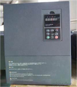
Frequency Inverter 3 phase VFD VSD
- Ref Price:
-

- Loading Port:
- China Main Port
- Payment Terms:
- TT OR LC
- Min Order Qty:
- -
- Supply Capability:
- -
OKorder Service Pledge
OKorder Financial Service
You Might Also Like

Specifications
1.220V Single Phase Variable Frequency Drive 2.2KW
2.Advanced control technology
3.Easy to operate
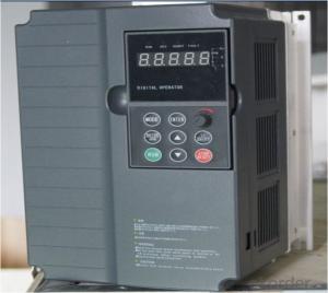
220V Single Phase Variable Frequency Drive 2.2KW
General
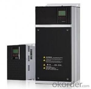
CNBM frequency inverter is a high-quality, multi-function,
low-noise variable frequency drive which is designed, developed and manufactured according to international standards.
It can meet different needs of industrial conditions.
The inverter applies advanced control technology of space voltage vector PWM, with functions of constant voltage control, power-off restart, dead zone compensation, automatic torque compensation, online modification parameter, high-speed impulse input, simple PLC and traverse.
Product Name:CMAX-VCG15/P18.5T3 ~ CMAX-VCG18.5/P22T3
Application
Textile: coarse spinner, spinning frame, wrap-knitting machine, loom, knitting machine, silk-spinning machine, etc.
Plastic: extruder, hauling machine, decorating machine, etc.
Pharmacy: mixer, roaster, etc.
Woodworking: engraving machine, sander, veneer peeling lathe, etc.
Papermaking: single type papermaking machine, etc.
Machine tool: non-core grinding machine, optical lens grinding machine, cutting mill, etc.
Printing: cloth-washing machine, dye vat, etc.
Cement: feeder, air blower, rotary furnace, mixer, crusher, etc
Fan and pump: kinds of fans, blowers and pumps
Specification
Item | Specification | |
Input | Input voltage | 220/380V±15% |
Input frequency | 47~63Hz | |
Output | Output voltage | 0~input voltage |
Output frequency | 0~600Hz | |
Peripheral interface characteristics | Programmable digital input | 4 switch input, 1 high-speed impulse input |
Programmable analog input | AI1: 0~10V input AI2: 0~10V input or 0~20mA input, | |
Programmable open collector output | 2 Output (3.7kW and above: 1 Open collector output) | |
Relay Output | 1 Output (3.7kW and above: 2 Relay output) | |
Analog output | 2 Output, one is 0~10V, another is 0~20mA or 0~10V | |
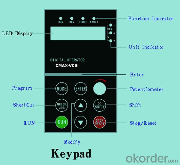
Keypad | Display:5-digit 8-section LED (Red), 2 indicators; parameter setting: 8 keys (including multi-function hot key ), 1 potentiometer | |
Technical performance characteristics | Control mode | All digital space voltage vector SVPWM algorism |
Overload capacity | G purpose: 150% rated current 60s P purpose: 120% rated current 60s | |
Speed ratio | 1: 100 | |
Carrier frequency | 1.0~10.0kHz | |
Torque compensation | Linear, multi-point, 1.3th power, 1.7th power, 2.0th power reduced torque; Compensation voltage range: automatic compensation and manual compensation 0.1~10% | |
Automatic voltage adjustment | It can automatically maintain output voltage constant when grid voltage fluctuates. | |
Automatic current adjustment | When the current is over current limit, under clocking automatically limits output current. | |
Function characteristics | Frequency setting mode | Keypad digital analog input, keypad potentiometer, impulse frequency, communication, multi-step speed and simple PLC, PID setting and so on, switch-over of setting modes. |
Simple PLC, multi-step speed control | 16-step speed control | |
Special function | Traverse control, length control, time control | |
QUICK/JOG key | User-defined multi-function hot key | |
Protection function | Over-current, Over voltage, under-voltage, over-heat, phase failure, over-load and motor over-load | |
Working condition | Installation site | Indoor, altitude of less than 1km, dust free, non-corrosive gases, no direct sunlight |
Application environment | -10°C~+40°C, 20~90%RH (no dew) | |
Vibration | Less than 0.5g | |
Storage temperature | -25°C~+65°C | |
Installation type | Wall-mounted type, floor cabinet type | |
Cooling mode | Air-forced cooling | |
- Q:Frequency converter, fault, contact action
- The frequency converter has 1-2 relay outputs, that is, digital output. By default, most of the output of the fault is the relay. The general definition of the 2 relays is defined as a running output and a fault output.This contact output and inverter circuit inside the electrical isolation, can use 24V, you can use 220V, you can use any lower than the voltage level of 500V to use this contact, according to the actual needs of love then why.
- Q:How can I learn the converter well?
- If you are engaged in maintenance or after sale, you must know the main circuit diagram of the converter, rectifier, filter, inverter. Some electronic components must know, from the main circuit is frequently such as varistors, charging resistance, pressure resistance, no sense of capacitor, filter capacitor, driving circuit of multiple optocoupler such as 2503503120316, this is referred to as the optocoupler and the role, you must know the pin. Because the maintenance process should always be to determine the quality of the device.
- Q:First of all, I would like to achieve the frequency converter with motor static linear acceleration, high-speed linear deceleration stop processFirst question: I say kind of situation, three paragraph speed start, 0.1hz---> high 30hz-->0.1hzSecond problem: manual speed instruction 1, speed 2, speed 3 instruction instruction I want to use PLC to control three speed motor with three reverse contact dry. I understand speed instruction 1 is switched on (2, 3 connected) transmission section set the frequency with the frequency segment set 0HZ123 AssociationThird questions: manual section, speed command, main frequency and STEP1-STEP7 stage setting frequency, I use PLC analog to the frequency main frequency setting, plus and deceleration, STEP1-7 are set 0, can achieve what I wantInitial contact frequency converter, home pointing
- Using PLC to analog converter control input frequency up to speed off from the requirements of the inverter frequency source set P-00 speed by 00 digital operation panel to analog frequency PLC given 0102 given frequency parameters can choose the set of 01 or 02 and the period of quick closing even P-17P-19 parameters affect analog control
- Q:What is the frequency converter AVR?
- When the input voltage deviation from the rated value, the function can keep the output voltage constant, so under normal circumstances should be AVR action, especially when the input voltage is higher than the rated value, to protect the motor from excessive voltage caused by long-term insulation damage or high magnetic density caused by excessive heating core.
- Q:What do you mean by the capacity of the inverter and the capacity of the motor?
- That's not the case at all"Capacity" and "power" are essentially different. Usually we say that a large transformer capacity is how much KVA, but not to say how much KW, because the two are not the same thing
- Q:What does the base frequency 60Hz represent in the inverter?
- The schematic diagram of the basic frequency parameters of the converter is shown in figure.Below the fundamental frequency, the output voltage of the converter varies with the output frequency, and the V/F= constant is suitable for constant torque load characteristics.Above the fundamental frequency, the output voltage of the inverter maintains the same voltage rating of the power supply, which is suitable for constant power load characteristics.
- Q:1, the frequency converter to the motor cable should be shielded cable? 2, whether there are specifications?
- Or, ask another question: "under what circumstances can the frequency converter go to the cable of the frequency conversion motor without using shielded cable?" Is there a "no need to use shielded cable" basis?
- Q:Knowledge, principle and operation method of frequency converter.
- Summary of the working principle of frequency converter:Before the work principle of frequency converter is understood, it may be possible to see why the inverter is sacred first Inverter is the frequency power supply (50Hz or 60Hz) converted to various frequency AC power supply, in order to realize the motor speed change operation of equipment. The control circuit controls the main circuit of the rectifier circuit will be converted into AC DC, DC intermediate circuit of the rectifier output smoothing filter, inverter circuit to DC and then reverse into alternating current (and core control circuit: AC - DC - AC the process). And the frequency conversion technology should be born with the need of AC motor stepless speed regulation. The working principle of formula to express the words is: n = 60 f (1 s) /p (1) - N - speed asynchronous motor; F -- asynchronous motor frequency; s - motor slip; P - pole motor. By formula (1), the speed n is proportional to the frequency f. As long as the frequency of F can be changed, the speed of the motor can be changed. When the frequency f changes within the range of 0 to 50Hz, the speed range of the motor is very wide. Frequency converter is to change the frequency of motor power to achieve speed regulation, is an ideal high efficiency, high performance speed control means.
- Q:What is the function of a frequency converter on an electric motor?
- Frequency converter integrates high voltage, high power transistor technology and electronic control technology, and has been widely used. The role of frequency converter is to change the frequency and amplitude of AC motor power supply, thus changing the period of its moving magnetic field, to achieve the purpose of smooth control of motor speed. The inverter speed control, makes the complex simple, most of the original work can only be done by a DC motor instead of frequency converter + AC squirrel cage induction motor, reduce the volume, reduce the maintenance rate, to a new stage of development of the transmission technology
- Q:What is the difference between a frequency converter and a servo controller?
- Frequency conversion technology: simple frequency converter can only adjust the speed of AC motor. At this time, it can be opened or closed loop. It depends on the control mode and frequency converter. This is the traditional V/F control mode. Now many of the inverter has been through the establishment of a mathematical model of AC motor, the stator magnetic field UVW3 phase into two current can control the motor speed and torque components of the inverter can now most famous brand of torque control are used in such a way to control the torque of each phase, UVW output current detection device Jiamoer the effect of sampling current feedback constitute a closed-loop negative feedback loop PID regulator; it can not only control the speed of the motor can also control the motor torque and speed control accuracy is better than v/f control, encoder feedback can also be added or not, and when the control precision and the response is much better.
1. Manufacturer Overview |
|
|---|---|
| Location | |
| Year Established | |
| Annual Output Value | |
| Main Markets | |
| Company Certifications | |
2. Manufacturer Certificates |
|
|---|---|
| a) Certification Name | |
| Range | |
| Reference | |
| Validity Period | |
3. Manufacturer Capability |
|
|---|---|
| a)Trade Capacity | |
| Nearest Port | |
| Export Percentage | |
| No.of Employees in Trade Department | |
| Language Spoken: | |
| b)Factory Information | |
| Factory Size: | |
| No. of Production Lines | |
| Contract Manufacturing | |
| Product Price Range | |
Send your message to us
Frequency Inverter 3 phase VFD VSD
- Ref Price:
-
- Loading Port:
- China Main Port
- Payment Terms:
- TT OR LC
- Min Order Qty:
- -
- Supply Capability:
- -
OKorder Service Pledge
OKorder Financial Service
Similar products
New products

Hot products

Hot Searches
Related keywords

