DBW SBW Compensated Voltage Stabilizer
- Ref Price:
-

- Loading Port:
- Shanghai
- Payment Terms:
- TT OR LC
- Min Order Qty:
- -
- Supply Capability:
- 10000pcs pc/month
OKorder Service Pledge
Quality Product, Order Online Tracking, Timely Delivery
OKorder Financial Service
Credit Rating, Credit Services, Credit Purchasing
You Might Also Like


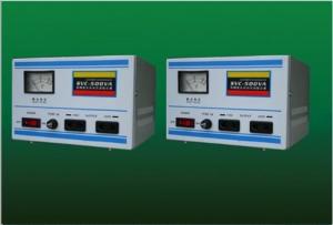
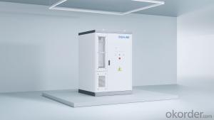
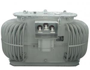
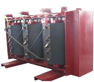
1.Application
DBW SBW compensated voltage stablilizer is a contact adjustable automatic voltage compen-sation high-power regulating power device. When voltage from supply network is varied or dueto loading current effect, it automatically regulates the output voltage to ensure the normal func-tion of the varied of electric equipments.
2.Specification
| Input voltage | Single phase: 220V; Three phases: 380V |
| Output voltage | Single phases: 220V±20% or 220V±30% Three phases four-line: 380V±20% or 380V±30% |
| Phase | Single phase; Three phases four-line |
| Frequency | 50Hz/60Hz |
| Response | within 1 sec.(against 10% input voltage deviation) |
| Efficiency | Better than 95% |
| Ambient temperature | -10oC~+40oC |
| Waveform | Non-lack fidelity waveform |
| Insulation restortion | Better than 5MΩ |
| Overload | Double rated current, one min |
| Protection | Overvoltage, overcurrent, feed phases |
3. Outline and packing
| Type | Outpower(kVA) | Outline(cm) | Weight(Kg) | Qty/CTN |
| DBW-20K | 20 | 70 x 50 x 135 | 283 | 1 |
| DBW-30K | 30 | 70 x 50 x 135 | 310 | 1 |
| DBW-40K | 40 | 70 x 50 x 135 | 330 | 1 |
| DBW-50K | 50 | 80 x 60 x 150 | 360 | 1 |
| DBW-60K | 60 | 80 x 60 x 150 | 380 | 1 |
| DBW-70K | 70 | 80 x 60 x 150 | 100 | 1 |
| DBW-80K | 80 | 90 x 70 x 170 | 430 | 1 |
| DBW-100K | 100 | 90 x 70 x 170 | 480 | 1 |
| SBW-50K | 50 | 80 x 62 x 135 | 350 | 1 |
| SBW-60K | 60 | 80 x 62 x 135 | 370 | 1 |
| SBW-100K | 110 | 85 x 52 x 150 | 420 | 1 |
| SBW-150K | 150 | 100 x 72 x 170 | 550 | 1 |
| SBW-180K | 180 | 100 x 72 x 170 | 570 | 1 |
| SBW-200K | 200 | 100 x 72 x 170 | 630 | 1 |
| SBW-225K | 225 | 110 x 80 x 180 | 660 | 1 |
| SBW-250K | 250 | 110 x 80 x 200 | 700 | 1 |
| SBW-300K | 300 | 110 x 80 x 210 | 740 | 1 |
| SBW-320K | 320 | 110 x 80 x 210 | 760 | 1 |
| SBW-400K | 400 | 110 x 80 x 210/2 | 1100 | 2 |
| SBW-500K | 500 | 110 x 80 x 210/2 | 1500 | 2 |
| SBW-600K | 600 | 110 x 80 x 210/2 | 2200 | 2 |
| SBW-800K | 800 | 85 x 100 x 220/3 | 2800 | 3 |
| SBW-1000K | 1000 | 85 x 100 x 220/3 | 3500 | 3 |
| SBW-1200K | 1200 | 85 x 100 x 220/3 | 4100 | 3 |
| SBW-1600K | 1600 | 110 x 110 x 220/4 | 5560 | 4 |
| SBW-2000K | 2000 | 110 x 110 x 220/4 | 7100 | 4 |
- Q:I need to run 12 amps through a 5-ohm electromagnet which means 60 volts must fall across it. I am building a power supply bridge rectifier circuit to fit my needs. I have a transformer capable of handling the wattage requirements but I am having trouble figuring out the amount of turns on the transformer to have on both the primary and secondary. The primary will be connected to an American outlet and I just don't understand how to get 60 volts DC out since the AC RMS voltage will be different than the rectified DC voltage.
- The transformer's primary should not disturbed, if possible. If not, then replace the primary wire using the same wire gauge and number of turns. The secondary winding needs a wire that handles about twice as much current as the primary's winding, which would require a wire that has twice the cross sectional area. I don't think that capacitor filtering of the bridge rectifier's output is necessary, but it would cause a lot of hum. If the capacitor is not used, the current and voltage feeding the magnet will be relative the average value (.63 of peak value), rather that the RMS value (.707 of peak value), Therefore, the peak value of the secondary winding would be 60/0.63 plus bridge rectifier drop or about 95 volts. Its RMS value is then 95*.707 67 volts and the turns ratio would be 67/102 .56 to 1.
- Q:I check the voltage between x1 and x2 I got 120v but between x1 and ground on primary I got 40v and between x2 and ground on Primary I have 50v, if I connect x2 to ground won't it short the transformer? Thank you
- What you see is normal, until the transformer is grounded the voltage floats. It is the same with the power for your house, the secondary of the transformer is normally grounded at the utility transformer, and at your ground rods, and to your water lines. X2 is the normal side grounded, although this has never made sense to me. You can imagine this, connecting one end of a flashlight battery to the frame of a car does nothing, you could then attach the other end of the battery to a light bulb, and the other bulb connection to the end of the battery or the frame, it only shorts if you connect the hot to the ground if you don't connect through a correctly rated load. Edit: Yes, ground it to the ground screw that the 208v ground wire is connected to, just to be clear, 208v connections H1 and H2 should not be grounded, and either x1 OR x2 needs be grounded, normally x2, grounding the transformer connection that is not connected to fuses.
- Q:Hi, I need a High Frequency( example~200khz) High voltage(200 000v) power supply at low microcurrent, I know that a Tesla coil fits the bill very easily . But I need to manually VARY the frequency(say from 100khz to 200khz ) while keeping the High voltage the same? Is this possible, Can some one guide me where I can buy or build this? Can I just for instance connect just a van de graaf or a rectified Tesla Coil to a function generator? If not what do I need to do to achieve what I want? I have been searching without help so your support is much appreciatedThanks
- The Tesla coil needs to operate at the same resonant frequency on both the primary and secondary sides of the loosely coupled transformer. The resonant frequency is set by the inductance and capacitance of each side. The problem is there are no high voltage solid state capacitors (varactor diodes like you see in r.f. receivers that adjust the tank circuit frequency) on the primary side, and no way to adjust the top hat toroid capacitor on the secondary side (unless maybe it was a mylar covered balloon with vacuum deposited aluminum that could be remotely inflated or deflated). So you are stuck with whatever high voltage capacitor and toroid top hat you have on hand, and the inductance of the coils you wind that ends up being the resonant frequency. Even then it takes a lot of fiddling to get both in tune to give the maximum voltage output. The input frequency to the primary coil (the 555 circuit used in the step up with the flyback transformer- its frequency was chosen solely due to the flyback's frequency design) has little to do with the primary's resonant frequency; again that is set by the capacitor used and the size and number of turns of the primary coil.
- Q:b)Describe an important industrial application of one of the above devices (apart from transformers)C)Explain how this device works-that is ,what the electricity actually does
- A transformer is a device that allows you to easily and efficiently convert an AC voltage to a different voltage. When you do this, the current is converted in the opposite ratio. For example, if you have a 100 volt 1 amp source and you convert it to a 1000 volt source, it will have capability of 0.1 amp. It is made by winding wires on iron cores. See the reference for details. It is very important for the transmission of AC power, as it can be changed to a very high voltage for efficient distance transmission, and back to low voltage for use in homes. .
- Q:A 120 kVA, 7000/277 V (What does this rating mean) distribution transformer has the following resistances and reactances: Rp 5.5 ohms Xp 6.5 ohms Rs 0.007 ohms Xs 0.008 ohms Rc 55 kohms Xm 15 kohms The excitation branch impedance are given referred to the low voltage side of the transformer: a) What's the equivalent circuit of the transformer referred to the low voltage side b) What's the the per unit equivalent circuit c) Assume that this is supplying rated load at 277V and 0.89 lagging power factor, What is the transformer input
- 120 kVA, 7000/277 V (What does this rating mean) Primary voltage rating: 7000 V, secondary voltage rating: 277 V, rated load: 120 kVA It is unclear whether this is a single-phase or three-phase transformer. You probably need to assume it is single-phase. The equivalent circuit of a 3-phase transformer is analyzed as one of three single-phase transformers that could be connected to make the equivalent Y-Y three-phase transformer. The secondary voltage, 277 V, is the line to neutral voltage for a 480 V, wye distribution system. That is a USA standard system voltage. The primary would be 12,124 V L-L, 7000 V L-N. That would a reasonable primary distribution system voltage. Referring the circuit to the low side means changing the primary component values to the equivalent secondary values and moving the ideal transformer to the primary side of the circuit as shown below. To change the primary impedance values, multiply by (Sec V/Pri V)^2.
- Q:I have a 34kv/380/500KVA transformer and it loads a pump of 450HP/2200V. Starting current reaches up to 1700 amps for around 3-4 seconds using a soft starter. The rated capacity of the transformer is 700amps and the pump running current is 689 amps.Any calculations to prove that the transformer is enough to provide the application would be a help.thanks.
- Damn, had to read the question before I realized it has NOTHING to do with Optimus Prime or Megatron. (*laughing*)
- Q:i have a transformer and i dont know anything about it. can someone help me with it.ps: i dont know how many turn the transformer have. dont the voltage either
- Transformers are used to increase/decrease Voltage and current depending on your requirements.Don;t forget whatever power you put in only will come out, so if you Impress x Voltage, and y Current across a transformer, it either increases voltage, while reducing current, or vice versa, since Power Voltage × Current, therefore, if you are going to increase current, output voltage reduces, and if you increase Voltage, output Current reduces.Here is a transformer picture google .in/images?um1hlenbiw1280bih663tbsisch:1sa1qelectrical+transformer+diagramaq0aqig7aqloqelectrical+transformer+gs_rfai If you follow this link, you will see a picture of a few transformers, with two windings, and is called a two phase Transformer. There are in general two types of transformers, Step up and Step down Transformers. Step up ones have little primary winding( The winding where you put in you power) compared to secondary windings(The output ).Since electricity has magnetic properties, it starts to Induce the other side, since it has more windings, more Voltage is induced, and since input power output power, if Voltage increases, output current reduces. ex.Input Voltage10V, Electrons that flow 10Amperes Ratio of Primary to secondary Winding 1:2 Output power 20V, Electrons that flow 5Amperes 10 into 10 20 into 5 This is a rough example to explain. There are numerous other factors that are needed to calculate Transformers, such as Impedance, Frequency of Alternating Current, Flux losses, Materials used to laminate the iron core, or any core, and so on. Hope I have helped
- Q:I remember a Transformers cartoon and there was like a gas in it and if the Autobots were in a place that the gas was in there, they would turn red and turn evil and fight each other. And also Optimus Prime was dead fist and then some Autobots bring him back to life And I think Rodimus has the matrix. What was that movie called?
- Yup, that was the episode in season three where Optimus Prime is brought back to life (after his death in the movie). The episode is called Return of Optimus Prime and is a two parter. The red stuff is rage and can pass if you get touched a la 28 days later. This is the episode that had Optimus return to life and get back the matrix from Rodimus (turning again back to Hot Rod). He unleashed the matrix to defeat the rage, but it empties the matrix of all it contained.
- Q:I'll be going to Peru for 2 weeks and I was wondering if I could plug in my electronics over there. I read that they have both North American and European outlets and the voltage is 220 V and 60 Hz. My iPod wall charger and phone charger say 100~240 V (and my laptop charger says 100-240 V) and 50/60 Hz. Would I need to buy a transformer while I'm there so my stuff doesn't get all burnt out?
- most south american and north american countries are the same plug sockets and voltage. also you can but anything there
- Q:From the following transformer, how would I calculate:a) the equivalent impedance on the low-voltage sideb) Converting the impedance found in (a) to it's per-unit quantities
- a) the turns ratio of the transformer is 20 to1 so to refer an HV side impedance to the LV side you divide it by the square of the turns ratio which in this case is 400 which gives: 0.001+j0.00025 ohms. b) There's a certain amount of freedom in doing this for you may define the per-unit impedance base however you want. It is however rather usual to define it as VA / I^2. Here I 5000/2400 2.083 amps So base impedance HV side 5000/2.83? 624 ohms making the given impedance (0.4+j0.1)/624 p.u. This p.u. value should be the same on either side of the transformer. Nice to see you around again but do I notice you haven't improved at saying please when you want someone to do something for you for nothing. If you can't learn that there's not much use in learning all these technical skills. You're going to remain a clumsy oaf!
1. Manufacturer Overview |
|
|---|---|
| Location | |
| Year Established | |
| Annual Output Value | |
| Main Markets | |
| Company Certifications | |
2. Manufacturer Certificates |
|
|---|---|
| a) Certification Name | |
| Range | |
| Reference | |
| Validity Period | |
3. Manufacturer Capability |
|
|---|---|
| a)Trade Capacity | |
| Nearest Port | |
| Export Percentage | |
| No.of Employees in Trade Department | |
| Language Spoken: | |
| b)Factory Information | |
| Factory Size: | |
| No. of Production Lines | |
| Contract Manufacturing | |
| Product Price Range | |
Send your message to us
DBW SBW Compensated Voltage Stabilizer
- Ref Price:
-
- Loading Port:
- Shanghai
- Payment Terms:
- TT OR LC
- Min Order Qty:
- -
- Supply Capability:
- 10000pcs pc/month
OKorder Service Pledge
Quality Product, Order Online Tracking, Timely Delivery
OKorder Financial Service
Credit Rating, Credit Services, Credit Purchasing
Similar products


New products

Hot products


Related keywords

