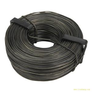
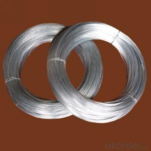
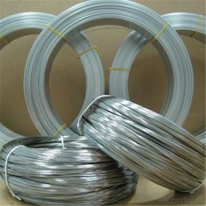
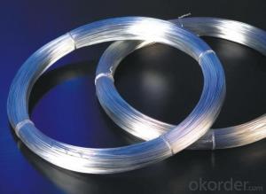
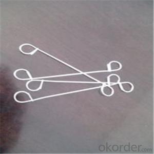
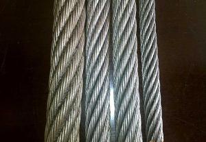
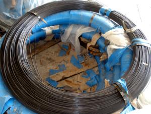
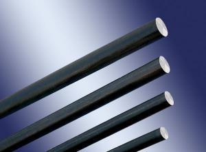
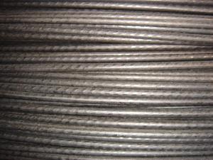
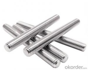
Class B Zinc Layer Of Electro Galvanized Wire
- Ref Price:
-

- Loading Port:
- China Main Port
- Payment Terms:
- TT OR LC
- Min Order Qty:
- -
- Supply Capability:
- -
OKorder Service Pledge
Quality Product, Order Online Tracking, Timely Delivery
OKorder Financial Service
Credit Rating, Credit Services, Credit Purchasing
You Might Also Like


Quick Details
| Steel Grade: | Standard: | Wire Gauge: | |||
| Place of Origin: | Type: | Application: | |||
| Alloy Or Not: | Special Use: | Zinc Purity: | 99.995% | ||
| Delivery: | Tensile Strength: | Diameter: | |||
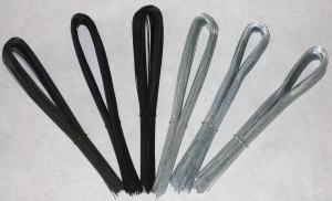
| Packing: |
Packaging & Delivery
| Packaging Detail: | Coil, Spool, Big Coil packing |
| Delivery Detail: | 20-30 days after signing the formal contracts |
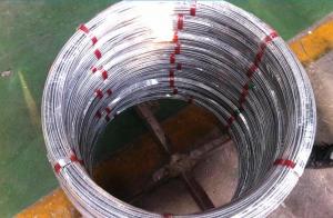
Specifications
1.ISO9001:2008 Certificate
2.Zinc coating:320--610g/m2
3.high quality attractive price
4.Diamter:2.0--6.0mm
- Q:A 41.7-kg sign is suspended by two wires, as the drawing shows. Wire 1 makes and angle of 42.2deg with the horizontal and wire 2 makes an angle of 58.8deg. Find the tension in wire 1 and wire 2.
- To solve this, you have to find 2 equations, because there are 2 unknowns. Assume, Tension in wire 1 = T1 Vertical component of T1 = T1 sin42.2 Horizontal component of T1 = T1 cos42.2 Tension in wire 2 = T2 Vertical component of T2 = T2 sin58.8 Horizontal component of T2 = T2 cos58.8 Since the sign board is in equilibrium, the forces must balance each other. Horizontally, the horizontal components of both forces are balancing each other. Therefore, T2 cos58.8 = T1 cos42.2 T2 = (T1 cos42.2) / (cos58.8) -------------------(1) For the vertical components of the wire, both are balancing the weight of the sign. T1 sin42.2 + T2 sin58.8 = (41.7)(9.8) T1 sin42.2 + T2 sin58.8 = 408.66N ----------------(2) Combine (1) into (2), T1 sin42.2 + (T1 cos42.2)(sin58.8) / (cos58.8) = 408.66 T1 ( sin 42.2 + cos 42.2 tan 58.8) = 408.66 T1 = 215.66N Subst T1 = 215.66N into (1), T2 = (T1 cos42.2) / (cos58.8) = 308.4N Hope it is correct ^^
- Q:Im cleaning up some of the wires in the engine bay and getting rid of ones i dont use. Right now theresthe pos side bat post runs down to the starter. From the starter there is a thicker wire and a skinny wire. In the thicker wire there is a wire that goes to the post on alternator. Both wires from starter run over to a relay maybe ithas a stud sticking out and has a wire that goes from the bottom of it to the fuse box. Im in middle of relocating the battery into the trunk so what wires can i eliminate and what wires have to go,to the battery?
- Like Mikey reported for starter and alternator it is not appropriate. in case you think of issues have been swapped there are various strategies over the 40+ years that Chev made the classic small block. Assuming that's a Chev motor there are in basic terms 2 starters and the version is the place the mounting bolts are. One version the bolts are in the present day for the time of from one yet another and the different form they're offset. most of the engine blocks have the two contraptions of holes so it relies upon on the flywheel which one is needed. Alternator could be slightly extra challenging to verify. countless strategies will bodily in superb condition then you definately've the pulley form, connector type and charm and orientation. you will be able to ought to snap some pictures and desire for an surprising guy on the aspects save or carry the previous one in and tournament it up.
- Q:A long horizontal wire carries a current of = 52 . A second wire, made of 1.00--diameter copper wire and parallel to the first, is kept in suspension magnetically 5.0 below.What is the magnitude of the current in the lower wire?
- The lower wire is kept in suspension magnetically means that the downward force of gravity is equal to the upward magnetic force. Its NOT an easy problem so we need to solve it in small steps. Let's find the two forces acting on the lower wire: (*) Downward force of gravity = mg = (volume) x (density) x (gravitational acceleration) = (pi r^2 L) x(8920)x(9.8) = 0.06896L We assume the radius of the wire is 0.5 mm or 0.0005m, copper density is 8960 N/m^3, gravitational acceleration = 9.8 m/s^2 (**) Upward magnetic force = mu(zero) x i(one) x i(two) x L / (2 pi d) = 2.08x10^(-4) L i(two) mu(zero) is a constant = 4 pi 10^(-7), i(one) is the current in the first wire = 52A, i(two) is the unknown current in the second wire, d is the distance between the wires = 5 mm or 0.005m The forces are equal, therefore 0.06896L = 2.08x10^(-4) L i(two) We divide both sides by L (the unknown length of the lower wire) and now we can solve for the current i(two) ANSWER: i(two) = 331.5 A
- Q:wires have been cut and i have 4 wires i dont know what do.what colors are for what?
- If your trying to wire a aftermarket radio into your car just go to best buy or any other car audio dealer and buy a wiring harness. It plugs directly into your stock wiring harness and on the opposite side has the correct colors of your aftermarket harness that came with the deck. All you have to do is color match and crimp.
- Q:cd wires tie into what color wires in your car
- if the harness is cut Car Radio Battery Constant 12v+ Wire: Orange Car Radio Accessory Switched 12v+ Wire: Yellow Car Radio Ground Wire: Black Car Radio Illumination Wire: Gray Car Stereo Dimmer Wire: Brown Car Stereo Antenna Trigger: Pink Car Stereo Amp Trigger Wire: N/A Car Stereo Amplifier Location: N/A Car Audio Front Speakers Size: N/A Car Audio Front Speakers Location: N/A Left Front Speaker Positive Wire (+): Tan Left Front Speaker Negative Wire (-): Gray Right Front Speaker Positive Wire (+): Light Green Right Front Speaker Negative Wire (-): Dark Green Car Audio Rear Speakers Size: N/A Car Audio Rear Speakers Location: N/A Left Rear Speaker Positive Wire (+): Brown Left Rear Speaker Negative Wire (-): Yellow Right Rear Speaker Positive Wire (+): Dark Blue Right Rear Speaker Negative Wire (-): Light Blue good luck and i hope this helps
- Q:Okay so I just finished replacing a stolen car radio, but I think I messed up the wiring... When I turn off the car the radio doesn't seem to save the presets I had... it resets the whole stereo... I think it has something to do with the wiring I did... When I installed the radio there were two 12+ volt wires... One said 12+ volt constant and was yellow, and the other said 12+ volt switch and was pink... Problem was when I wired only the yellow one the car stereo wouldn't work, so I tried the pink one and that didn't work.. SO thinking I was clever I wired both to the 12+ volt and VOILA the radio turned on... Problem is I don't think that's how I was supposed to wire it... I have a '97 Honda accord Ex and I don't know if that's what I was supposed to do... :#92;
- A car stero needs 3 main wires Constant Power (Normally Yellow) for memory like radio presets Switched Power (Normally Red) Switched by the cars ignition so your radio turns on/off with your keys You can wire these two together as long as its a constant feed, youll just have to turn it off yourself... but then it will work when the ignition is off as well that way and Earth (Normally black) The rest of the wires if you pay attention you can pair them up to form the front speakers and rear speakers, it looks to me like... this is going to take sometime to get my head around ill edit it ounce ive worked it out... Either way youv got your red and black there thats positive and negative, it will turn on with those. How many speakers in the car, and are they orginal, I asume all wires have an open end? the four black and white ones sound like someones added them, and put non orginal speakers in.
- Q:I have a universal 02 sensor 4 wire (black, black, white and blue) the stock is white black and grey how do I wire it? thanks :)
- Keep in mind the sensor has a signal wire, a ground wire and a heater wire (or wires). Good luck!
- Q:What type of wire do i need to install a normal inside wall outlet? Do i have to use solid copper wire?
- If the circuit breaker feeding the receptacle is 15 amps, you must use a #14 minimum size. if it is a 20 amp breaker, you must use a #12 minimum. You can use either solid or twisted. TexMav
- Q:i am installing a headunit, i connected all the wires the match, but i have some left over that i am confused about. from the wires that plug into the radio there is the antenna wire, the remote wire, and the ground with a washer to screw it down, and from the other is set of wires is a solid orange wire, which i have no idea where it goes to. so i connected the remote to the orange wire and didn't hook up the antenna to anything, and bolted down the ground wire. I'm wondering why i have 2 ground wires, and what the orange wire is and what do i connect to it?
- if its basically static, your audio gadget are effective, verify that not one of the wires are touching, whether its basically one + touching a - the entire gadget will sound undesirable (different than for the sub which gets its sign from a different source. verify at the back of the cd participant and in case you're able to desire to get rid of each and each speaker a million by using a million.
- Q:There are two switches – the left is for the fan, the right is for the light. They operate independently. I want to replace the light switch with one that has a motion sensor.There are four sets of bundled wires coming out of the back of the box. Each bundle has a white, a black, and a copper wire.Two black wires come out of each switch. The top wires go into two of the bundles in the back of the box, the bottom wires are connected with each other and with two more black wires coming out of the other two bundles coming out of the back of the box.All the white wires are twisted together with a red cap. All of the copper wires are twisted together with another red cap.My motion sensor has a red, black, green and yellow wire. The directions say the yellow wire is not used, because this is not a 3-way light. Is there a straightforward way to do this?
- Sure is!. You wire it exactly the way the instructions say to. Which is to use the 2 wires on the existing switch. The bare wire on the switch (if present) is the ground and goes to the green. Just like the instructions say. You are apparently letting all those other wires scare you. The motion sensor is nothing more than an automatic switch. It does the same thing the existing switch does, using the exact same wires. Do Not touch any of the existing splices. Look again at the instructions. Take a deep breath and have at. I've been in control cabinets with Hundreds of wires in them. I ignored all but the ones I need to work on. Other wise I would still be there trying to figure it out! (chuckle)
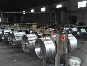
1. Manufacturer Overview |
|
|---|---|
| Location | |
| Year Established | |
| Annual Output Value | |
| Main Markets | |
| Company Certifications | |
2. Manufacturer Certificates |
|
|---|---|
| a) Certification Name | |
| Range | |
| Reference | |
| Validity Period | |
3. Manufacturer Capability |
|
|---|---|
| a)Trade Capacity | |
| Nearest Port | |
| Export Percentage | |
| No.of Employees in Trade Department | |
| Language Spoken: | |
| b)Factory Information | |
| Factory Size: | |
| No. of Production Lines | |
| Contract Manufacturing | |
| Product Price Range | |
Send your message to us
Class B Zinc Layer Of Electro Galvanized Wire
- Ref Price:
-
- Loading Port:
- China Main Port
- Payment Terms:
- TT OR LC
- Min Order Qty:
- -
- Supply Capability:
- -
OKorder Service Pledge
Quality Product, Order Online Tracking, Timely Delivery
OKorder Financial Service
Credit Rating, Credit Services, Credit Purchasing
Similar products

New products


Hot products